Strategies for Addressing Foreign Body Reaction in Implantable Biomaterials: From Molecular Mechanisms to Clinical Translation
This article provides a comprehensive analysis of the foreign body reaction (FBR) to implantable biomaterials, a major challenge limiting the long-term success of medical devices.
Strategies for Addressing Foreign Body Reaction in Implantable Biomaterials: From Molecular Mechanisms to Clinical Translation
Abstract
This article provides a comprehensive analysis of the foreign body reaction (FBR) to implantable biomaterials, a major challenge limiting the long-term success of medical devices. Targeting researchers, scientists, and drug development professionals, we synthesize current understanding from foundational biology to advanced application strategies. The content systematically explores the complex inflammatory and fibrotic processes driving FBR, evaluates material design and surface modification approaches to mitigate immune activation, discusses troubleshooting for device failure, and presents comparative validation data for emerging biomaterials. By integrating the latest research on molecular signaling, material properties, and preclinical evaluation, this review serves as a strategic resource for developing next-generation implants with enhanced biocompatibility and functionality.
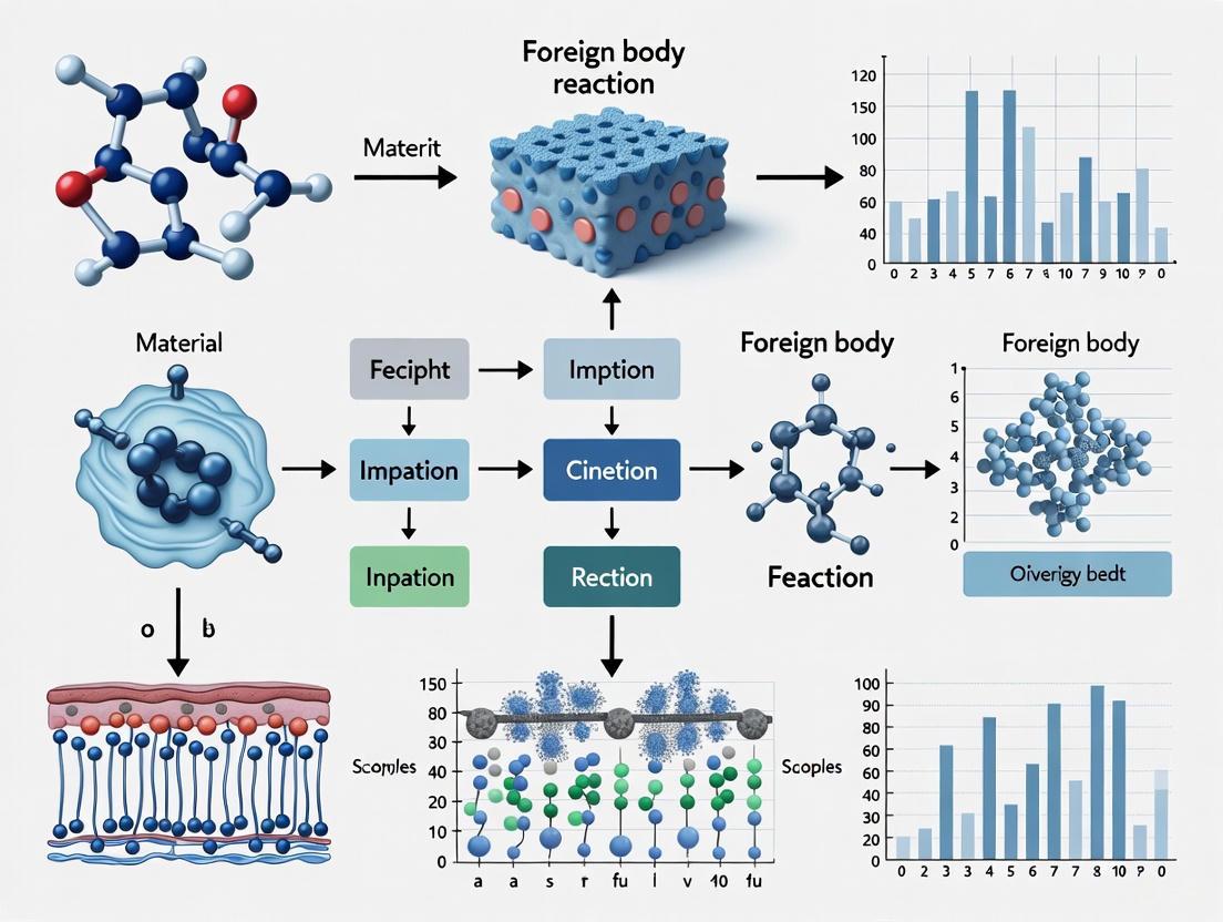
Decoding the Foreign Body Reaction: Cellular Mechanisms and Molecular Pathways
The Stage-by-Stage Foreign Body Reaction (FBR) Timeline
The Foreign Body Reaction (FBR) is an inevitable host response to implanted materials, initiated by tissue injury and marked by a cascade of inflammatory and fibrotic processes [1]. The table below details the sequence of events from implantation to final encapsulation.
| Stage | Time Post-Implantation | Key Cells Involved | Primary Processes & Molecular Signals |
|---|---|---|---|
| 1. Protein Adsorption | Seconds to Minutes | Blood proteins (fibrinogen, vitronectin, fibronectin) [2] | Adsorption of blood and interstitial fluid proteins to the biomaterial surface [2]. |
| 2. Acute Inflammation | Hours to Days | Neutrophils, Mast Cells [2] | Recruitment of innate immune cells; release of cytokines and enzymes from neutrophils attempting to phagocytose the material [2]. |
| 3. Chronic Inflammation / Macrophage Activity | Days to Weeks | Macrophages, Foreign Body Giant Cells (FBGCs) [2] | Macrophage recruitment, activation, and fusion to form FBGCs; enzyme release; IL-4 from mast cells and T cells induces FBGC formation [2]. |
| 4. Fibrous Encapsulation | Weeks to Months | Fibroblasts, Myofibroblasts [1] | Deposition of a dense, largely avascular collagenous matrix (fibrous capsule) around the implant, isolating it from the host tissue [2] [1]. |
FBR Troubleshooting FAQs
Why is my implant surrounded by a thick, avascular fibrous capsule?
This is the hallmark end-stage of the classic Foreign Body Reaction. The fibrous capsule forms as a result of the body's attempt to isolate the implant [2] [1]. The thickness and density of the capsule can be influenced by the biomaterial's properties.
- Potential Causes:
- Material Properties: Synthetic polymers with specific surface topographies, high stiffness, or non-porous structures can promote a pro-fibrotic macrophage response, leading to excessive collagen deposition [2].
- Persistent Inflammation: A prolonged chronic inflammation phase, dominated by pro-inflammatory (M1) macrophages and FBGCs, drives the fibrotic cascade [2].
- Solutions:
- Modify Material Architecture: Consider using porous scaffolds, as they have been shown to elicit less severe inflammation and thinner fibrous encapsulation than solid materials [2].
- Explore Natural Polymers: Natural polymers like silk or collagen often elicit a less severe FBR compared to some synthetics [2].
My drug-eluting implant shows variable release kineticsin vivo. Could the FBR be the cause?
Yes, the developing fibrotic capsule can act as a physical barrier to drug diffusion.
- Evidence: A 2025 study found that the early, acute FBR phase can temporarily modulate the release of large molecules (like IgG, 150 kDa) from reservoir-based implants. However, the impact on small molecule drugs (like islatravir, 293 Da) at steady-state may be negligible [3].
- Investigation Steps:
How do I select a polymer for a neural interface to minimize FBR?
Biocompatibility is crucial for neural implants, as the FBR can lead to glial scarring and loss of device function [4].
- Recent Findings: A 2025 comparative study of ten polymers for neural interfaces ranked several materials based on toxicity and tissue response [4].
- Recommendations:
- Promising Materials: Polyimide (PI) showed the highest compatibility. Polylactide (PLA), Polydimethylsiloxane (PDMS), and Thermoplastic Polyurethane (TPU) also showed lower pathological responses and are promising for neural applications [4].
- Material to Avoid: Polyethylene Glycol Diacrylate (PEGDA) exhibited cytotoxic effects, low cell adhesion, and stimulated a strong FBR with fibrosis, making it unsuitable for long-term neural interfaces [4].
Myin vitrocytotoxicity results do not match the FBR severity I seein vivo. Why?
This is a common challenge because the FBR is a complex, multi-cellular process that cannot be fully recapitulated in a simple cell culture model.
- The Reason: In vitro tests typically assess baseline toxicity and cell adhesion. In contrast, the in vivo FBR involves a dynamic interplay between innate immune cells, adaptive immune cells (T cells, B cells), and tissue repair cells, all influenced by the mechanical and chemical properties of the implant [2] [4].
- Solution: Use in vitro data for initial screening but always validate key materials in an in vivo model to assess the full spectrum of the FBR, including fibrous encapsulation [4].
Key Experimental Protocols for FBR Characterization
Protocol 1: Histological Evaluation of the Fibrotic Capsule
This protocol is essential for quantifying the end-stage FBR around an explanted device.
- Explanation and Fixation: Carefully remove the implant with surrounding tissue at the desired time point (e.g., 2 and 4 weeks for early/chronic phases). Immediately place the tissue in 10% neutral buffered formalin for 48 hours.
- Processing and Sectioning: Dehydrate the fixed tissue through a graded series of ethanol, clear with xylene, and embed in paraffin wax. Section the block into 5 µm thick slices using a microtome.
- Staining:
- H&E Staining: For general tissue morphology and to identify key cell types (macrophages, FBGCs, fibroblasts).
- Masson's Trichrome Staining: To specifically visualize and quantify the collagen-rich fibrous capsule (stained blue) surrounding the implant.
- Imaging and Analysis: Image stained sections under a light microscope. Use image analysis software (e.g., ImageJ) to measure the thickness of the fibrous capsule at multiple locations around the implant.
Protocol 2: In Vitro Macrophage Fusion Assay (FBGC Formation)
This assay investigates the potential of a biomaterial to induce the formation of foreign body giant cells, a hallmark of the FBR.
- Material Preparation: Sterilize your biomaterial samples (e.g., polymer films) and place them in the wells of a culture plate.
- Cell Seeding: Isolate primary human monocyte-derived macrophages or use a macrophage cell line (e.g., RAW 264.7). Seed the cells onto the material surfaces at a defined density.
- Stimulation with Cytokines: Culture the macrophages in the presence of recombinant IL-4 (20 ng/mL) and GM-CSF (10 ng/mL) for 7-14 days to promote fusion. Refresh the media and cytokines every 2-3 days.
- Staining and Quantification: After the incubation period, fix the cells and stain for multinucleated cells. A common method is to stain F-actin with phalloidin (to visualize the cytoskeleton) and counterstain nuclei with DAPI. Count the number of FBGCs (defined as cells containing three or more nuclei) per viewing field under a fluorescence microscope.
FBR Signaling Pathway and Cellular Interactions
FBR Cellular and Molecular Signaling
The Scientist's Toolkit: Essential Research Reagents & Materials
| Reagent / Material | Function / Role in FBR Research | Example Application |
|---|---|---|
| Polylactide (PLA) | A biodegradable synthetic polymer used for implants and drug delivery systems [2] [3] [4]. | Fabrication of resorbable scaffolds and drug-eluting implants; studying material-dependent FBR [3] [4]. |
| Polyimide (PI) | A polymer noted for high biocompatibility, especially in neural interfaces [4]. | Used as the insulating substrate in chronic neural implants to minimize FBR and glial scarring [4]. |
| Polyethylene Glycol Diacrylate (PEGDA) | A hydrogel polymer known to elicit a strong FBR; useful as a positive control for severe reactions [4]. | Serves as a benchmark for comparing cytotoxicity and fibrotic responses of new materials [4]. |
| Recombinant IL-4 Cytokine | Key cytokine that induces macrophage fusion into Foreign Body Giant Cells (FBGCs) [2]. | Used in in vitro macrophage culture assays to stimulate and study FBGC formation [2]. |
| Recombinant TGF-β Cytokine | A primary fibrogenic cytokine that drives fibroblast activation and collagen production [2]. | Used to stimulate fibroblast-to-myofibroblast differentiation in in vitro models of fibrosis. |
| Antibodies: CD68 (Macrophages) | Immunohistochemical marker for identifying and quantifying macrophages in tissue sections. | Staining of tissue sections from explants to characterize the intensity of the macrophage response. |
| Antibodies: α-SMA (Myofibroblasts) | Immunohistochemical marker for activated myofibroblasts, the key collagen-producing cells. | Used with tissue sections to quantify the number of activated myofibroblasts in the fibrous capsule. |
| Masson's Trichrome Stain | Histological stain that colors collagen fibers blue, allowing visualization of the fibrous capsule. | Standard protocol for measuring the thickness and density of the collagenous capsule around an implant [3]. |
Frequently Asked Questions (FAQs)
Q1: What is the sequential order of key immune cell recruitment following biomaterial implantation? The foreign body response follows a tightly orchestrated sequence. Neutrophils are the first responders, peaking within 24-48 hours post-implantation. They are followed by monocytes which differentiate into macrophages. Macrophages subsequently undergo fusion to form foreign body giant cells (FBGCs), a process that characterizes the chronic inflammatory phase [5] [6].
Q2: Why do my in vitro FBGC formation experiments yield inconsistent results? Inconsistency is a major challenge, primarily due to a lack of standardized protocols. A 2025 review highlights significant variability in critical parameters, including cell origin and type, culture media and sera, fusion-inducing factors (e.g., IL-4, IL-13 concentration), and seeding density. This variability severely hampers cross-study comparisons and reproducibility [7] [8].
Q3: What are the primary consequences of FBGC formation on implant functionality? FBGCs are associated with several detrimental outcomes. They contribute to the degradation of bio-resorbable materials through extracellular processes and the formation of a dense, avascular fibrous capsule. This capsule can isolate the implant, impairing its function by blocking molecular transport (e.g., in biosensors or drug delivery devices) and preventing vascularization, ultimately leading to implant failure [9] [5] [10].
Q4: Beyond chemical composition, what implant properties influence the foreign body reaction? The physico-chemical properties of the implant surface are critical regulators of the immune response. Key parameters include surface topography/roughness, mechanical stiffness, wettability, and surface chemistry. These properties dictate the initial adsorption of plasma proteins, which in turn mediates subsequent immune cell adhesion and activation [9] [5] [10]. Recent research also highlights that mechanical stress from the implant can activate specific proteins like RAC2 in immune cells, driving an overactive fibrotic response [11].
Troubleshooting Guide: Common Experimental Challenges
Inconsistent FBGC Formation In Vitro
This table summarizes common problems and evidence-based solutions for FBGC culture.
| Problem Description | Potential Causes | Recommended Solutions & Methodological Standards |
|---|---|---|
| Low Fusion Rate | • Incorrect cytokine type/concentration• Suboptimal cell seeding density• Inadequate culture surface | • Use IL-4 or IL-13 as primary fusogens [10].• Standardize seeding density; common range 50,000 - 200,000 cells/cm² [7] [8].• Use RGD-modified surfaces to improve macrophage adhesion and fusion competency [10]. |
| High Variability Between Assays | • Lack of protocol standardization• Different cell sources (e.g., primary vs. cell lines)• Inconsistent culture media/serum batches | • Adopt a defined, standardized protocol across experiments [7] [8].• Document cell source and passage number meticulously.• Use the same batch of serum and media components for a single study. |
| Difficulty in Quantification | • Inconsistent read-outs and definitions• Lack of clear criteria for what constitutes an FBGC | • Define FBGCs by a minimum number of nuclei (e.g., ≥3 nuclei per cell) [7].• Use standardized metrics like fusion index [(Number of nuclei in FBGCs / Total number of nuclei) × 100] [8]. |
Uncontrolled Fibrosis in Animal Models
This table outlines strategies to mitigate fibrosis, a key consequence of the FBR.
| Problem Description | Biomaterial Design Strategies | Pharmacological / Biological Strategies |
|---|---|---|
| Excessive Fibrous Encapsulation | • Modify surface topography: Introduce micro/nano-scale features to reduce biofouling and cell adhesion [5].• Tune mechanical stiffness to better match the target tissue (e.g., soft for neural interfaces) [5] [4].• Use natural materials (e.g., HA, collagen) which may elicit a favorable immune response [6]. | • Local delivery of anti-fibrotic agents (e.g., RAC2 inhibitors). RAC2 is a protein highly expressed in severe FBR and its blockade reduced FBR in animal models by up to three-fold [11]. |
| Chronic Inflammation at Implant Site | • Design surfaces that promote macrophage polarization towards the anti-inflammatory, pro-healing M2 phenotype [5] [12].• Use coatings with immunomodulatory factors to create a pro-regenerative microenvironment [12]. | • Not yet widely implemented; focus remains on biomaterial-centric approaches to guide innate immune response. |
Detailed Experimental Protocols
Protocol: Analyzing the Acute Neutrophil Response to Biomaterials
This protocol is adapted from an established in vitro model for comprehensive characterization of neutrophil responses [6].
1. Biomaterial Preparation:
- Select a panel of biomaterials representing a range of properties (e.g., THA, Col, GelMA, PCL, TCP).
- For hydrogel materials like Tyramine-functionalized Hyaluronic Acid (THA): a. Reconstitute the polymer conjugate in PBS at 2.5% (w/v) with 0.6 U/mL Horseradish Peroxidase (HRP). b. Rotate the solution overnight at 4°C. c. Initiate gelation by adding 1.3 mM hydrogen peroxide (H₂O₂), mix homogeneously, and cast into well plates. d. Incubate at 37°C and 5% CO₂ for 10 minutes to form the hydrogel.
- For all materials, wash the prepared surfaces with PBS 3x before cell seeding.
2. Neutrophil Isolation and Seeding:
- Isolate human primary neutrophils from peripheral blood using standard density gradient centrifugation.
- Seed neutrophils onto the biomaterial-coated surfaces at a defined density.
3. Functional Read-Outs (4-24 hours post-seeding):
- Cell Survival: Quantify neutrophil apoptosis via flow cytometry (e.g., Annexin V/PI staining).
- Oxidative Burst: Measure superoxide anion production.
- Granule Release: Quantify enzymes like Myeloperoxidase (MPO) and Neutrophil Elastase in the supernatant via ELISA.
- Cytokine Secretion: Analyze a broad panel of chemokines, cytokines, and fibrogenic factors (e.g., using Olink proximity extension assay).
Protocol: Inducing and Quantifying Foreign Body Giant Cell (FBGC) Formation
This protocol synthesizes common methods, emphasizing the need for standardization [7] [8] [10].
1. Macrophage Culture and Priming:
- Use primary human monocyte-derived macrophages (hMDMs) or a murine macrophage cell line like J774.
- Culture cells in appropriate media supplemented with 10% FBS and differentiating agents (e.g., M-CSF for hMDMs).
- To induce fusion competency, add recombinant IL-4 or IL-13 at a concentration of 20 ng/mL. Refresh the cytokine every 2-3 days.
2. Critical Culture Parameters for Standardization:
- Seeding Density: Plate cells at a density of 50,000 - 200,000 cells/cm².
- Culture Surface: Pre-coat plates with RGD-containing peptides or proteins to enhance adhesion if the biomaterial itself is not being tested.
- Culture Duration: Maintain cultures for 7-14 days to allow for robust FBGC formation.
3. Quantification and Analysis:
- Fusion Index: Calculate using the formula: (Number of nuclei in FBGCs / Total number of nuclei) × 100. Count only cells with ≥3 nuclei as FBGCs.
- Immunostaining: Confirm FBGC identity by staining for specific biomarkers like DC-STAMP.
- Morphological Analysis: Use light microscopy to assess the extent of cytoplasmic spreading and the number of nuclei per FBGC.
Signaling Pathways and Cellular Workflows
Cellular Timeline of Foreign Body Response
This diagram illustrates the key stages and cellular players in the FBR following biomaterial implantation.
Signaling Pathway for Macrophage Fusion into FBGCs
This diagram details the key molecular signals that drive macrophage fusion and FBGC formation.
The Scientist's Toolkit: Research Reagent Solutions
This table lists essential reagents and materials used in studying the foreign body response, based on the cited methodologies.
| Reagent / Material | Function / Application in FBR Research | Key Considerations |
|---|---|---|
| Recombinant IL-4 / IL-13 | Primary cytokines to induce macrophage fusion competency and drive FBGC formation in vitro [10]. | Concentration (e.g., 20 ng/mL) and timing are critical. Human vs. murine models may require different protocols [7] [8]. |
| RGD-Modified Surfaces | Synthetic surfaces containing Arg-Gly-Asp (RGD) peptides to enhance macrophage adhesion, a critical step prior to fusion [10]. | Improves reproducibility of cell adhesion compared to non-functionalized surfaces. |
| Primary Human Neutrophils | Isolated from peripheral blood for studying the acute phase of the FBR to biomaterials [6]. | Requires fresh isolation for each experiment. Functional assays (oxidative burst, NETosis) are time-sensitive. |
| Polymer Scaffolds (e.g., PCL, PLA, PDMS) | Used as 3D implant phantoms for in vitro and in vivo testing of biocompatibility and FBR [4]. | Surface properties (topography, stiffness) must be carefully controlled as they heavily influence the immune response [5]. |
| Antibodies for Flow Cytometry (e.g., anti-CD68, anti-DC-STAMP) | Identification and quantification of macrophage phenotypes and fusion markers [10]. | Enables distinction between M1 (pro-inflammatory) and M2 (pro-healing) macrophage populations. |
| ELISA Kits (for MPO, Elastase, Cytokines) | Quantification of neutrophil granule release and inflammatory cytokine secretion in response to biomaterials [6]. | Provides quantitative data on the intensity of the acute inflammatory response. |
Molecular Signaling and Cytokine Networks in Chronic Inflammation
Core Concepts: Foreign Body Reaction (FBR) and Molecular Signaling
What is the Foreign Body Reaction (FBR) and why is it critical in implant research?
The foreign body reaction (FBR) is an inevitable host response to implanted materials, initiated by tissue injury and marked by a cascade of inflammatory and fibrotic processes [1]. Following implantation, local tissue damage triggers acute inflammation, characterized by immune cell recruitment and activation. Over time, this response advances to a chronic fibrotic phase marked by dense extracellular matrix deposition and fibrous capsule formation, which can encapsulate and functionally isolate the implant [1] [13]. Both the early inflammatory and late fibrotic stages of FBR can severely impair the performance and longevity of implants [14]. For nerve neuroprosthetics, this is particularly problematic as FBR disrupts the intimate implant-tissue interface required for detecting tiny electrical signals or stimulating specific axons [14].
What are the key molecular signaling pathways governing chronic inflammation in FBR?
Chronic inflammation in FBR is governed by a dynamic and multifaceted network of molecular signaling pathways, cellular mechanosensing mechanisms, and intercellular communication [1]. Key signaling cascades include:
- NF-κB pathway: A primary regulator of inflammation, controlling the expression of pro-inflammatory genes.
- MAPK pathway: Involved in cellular responses to inflammatory stimuli.
- JAK-STAT pathway: Critical for cytokine signaling and immune cell differentiation.
- Inflammasome pathways: Drive the activation of inflammatory cytokines like IL-1β. Other relevant pathways include Toll-like receptor (TLR), arachidonic acid, complement system, and hypoxia-inducible factor (HIF) pathways [15]. A deeper molecular understanding is critical for the rational design of next-generation biomaterials that mitigate adverse host responses and improve biocompatibility [1].
The diagram below illustrates the core signaling pathways and cytokine networks involved in the Foreign Body Response.
Troubleshooting Guides & FAQs
Frequently Asked Questions (FAQs)
Q1: What is the significance of the "Vroman effect" in the initial stages of FBR? The Vroman effect describes the dynamic process of protein adsorption and desorption on an implant surface immediately following implantation [13]. Smaller proteins like albumin are initially adsorbed but are progressively replaced by larger proteins such as fibrinogen, fibronectin, and immunoglobulins [13] [14]. This initial protein layer is a critical determinant of the subsequent cellular response, as cells interact with the implant through these adsorbed proteins via specific adhesion receptors like αMβ2 integrin [13] [14].
Q2: Which cytokines are pivotal for the differentiation of CD4+ T cells in chronic inflammatory responses? CD4+ T cell differentiation is orchestrated by specific cytokine milieus and JAK-STAT signaling pathways [16] [17].
- Th1 cells: Driven by IL-12 (activates Stat4) and IFN-γ.
- Th2 cells: Driven by IL-4 (activates Stat6).
- Th17 cells: Differentiation requires TGF-β and IL-6 (which activates Stat3). IL-23 is also crucial for Th17 cell expansion and maintenance [16].
- Induced Treg (iTreg) cells: Also require TGF-β, but development is favored in the absence of inflammatory cytokines like IL-6 and the presence of factors like retinoic acid [16] [17].
Q3: How do biomaterial surface properties influence the foreign body reaction? Biomaterial surface properties—including chemical composition, topography, stiffness (Young's modulus), and morphology—play a crucial role in modulating the foreign body reaction, particularly in the first 2-4 weeks after implantation [13] [4]. These properties directly influence protein adsorption, monocyte/macrophage adhesion, and macrophage fusion into foreign body giant cells (FBGCs) [13]. For neural interfaces, matching the stiffness of the implant to the brain tissue (~1 kPa) is a key strategy to reduce mechanical mismatch and mitigate FBR [4].
Troubleshooting Experimental Challenges
Problem: High variability in cytokine measurements from cell culture supernatants.
- Potential Cause 1: Instability in fluidics during sample acquisition on a flow cytometer.
- Solution: Visualize time versus scatter/fluorescence to control for data stability over time and exclude invalid data [18].
- Potential Cause 2: Presence of dead cells or aggregates.
- Solution:
- Potential Cause 3: Non-specific binding via Fc receptors.
- Solution: Use an Fc block reagent or add serum (e.g., FBS) to block these interactions before antibody staining [18].
Problem: Inconsistent macrophage fusion and FBGC formation in in vitro models.
- Potential Cause: Inconsistent cytokine milieu. The cytokine environment is critical for macrophage fusion.
- Solution: Ensure the presence of key cytokines such as IL-4 and IL-13, which are potent inducers of macrophage fusion and FBGC formation [13]. Validate cytokine concentrations in your culture media.
Problem: Poor cell adhesion on polymer scaffolds for biocompatibility testing.
- Potential Cause: Unsuitable surface morphology or toxic compound release.
- Solution:
Experimental Protocols & Data
Detailed Protocol: Intracellular Cytokine Staining (ICS) and Flow Cytometry
This protocol is essential for analyzing cytokine production at the single-cell level, allowing researchers to phenotype immune cells and their functional states within the FBR microenvironment [18].
Cell Stimulation & Cytokine Accumulation:
- Stimulate cells (e.g., isolated from peri-implant tissue) in vitro with an appropriate stimulus (e.g., PMA/Ionomycin, specific antigens).
- Add a protein transport inhibitor (e.g., Brefeldin A or Monensin) to the culture medium to inhibit cytokine secretion, leading to intracellular accumulation. The choice of inhibitor can depend on the cytokines of interest [18].
- Incubate for 2-12 hours at 37°C. Note: Incubation periods longer than 6 hours with Brefeldin A may decrease cell viability [18].
Cell Harvest and Surface Staining:
- Harvest the cells and wash.
- Stain with a viability dye to exclude dead cells.
- Stain for cell surface markers (e.g., CD45 for leukocytes, CD11b for monocytes/macrophages, CD3 for T cells) to define cell populations. Use pre-optimized fluorochrome-antibody combinations [18].
Fixation and Permeabilization:
- Fix the cells using a formaldehyde-based fixative.
- Permeabilize the cells using a detergent-based permeabilization buffer to allow intracellular antibodies to access cytokines.
Intracellular Staining:
- Incubate cells with fluorochrome-conjugated antibodies against cytokines of interest (e.g., IFN-γ, TNF-α, IL-4, IL-17, IL-10).
- Wash thoroughly to remove unbound antibody.
Flow Cytometric Analysis:
- Resuspend cells in buffer and acquire data on a flow cytometer.
- Set up instrument using compensation controls and gating controls to distinguish positive and negative populations [18].
- Analyze data using single-parameter histograms and dual-parameter plots. The median fluorescence intensity is a robust indicator of central tendency [18].
The workflow for this protocol is summarized in the following diagram:
Quantitative Data: Polymer Toxicity and Tissue Response
The following table summarizes quantitative data from a comparative study of polymer toxicity and tissue response, providing key metrics for material selection in implant design [4].
Table 1: In vitro and in vivo assessment of polymer biocompatibility for neural interfaces [4].
| Polymer Material | Cell Adhesion (Neural PC-12) | Cell Adhesion (Fibroblast NRK-49F) | Cytotoxicity | Foreign Body Reaction (in vivo) |
|---|---|---|---|---|
| Polyimide (PI) | High | High | Low | Lowest; minimal fibrosis |
| Polylactide (PLA) | Moderate | Moderate | Low | Low |
| Polydimethylsiloxane (PDMS) | Moderate | Moderate | Low | Low |
| Thermoplastic Polyurethane (TPU) | Moderate | Moderate | Low | Low |
| Polyethylene Glycol Diacrylate (PEGDA) | Low | Low | High | High; significant fibrosis & multinucleated cells |
Key Signaling Pathways in Chronic Inflammation and FBR
The table below details the core signaling pathways, their roles in inflammation, and associated therapeutic targets relevant to modulating the FBR.
Table 2: Key inflammatory signaling pathways and their therapeutic significance [1] [15] [16].
| Signaling Pathway | Key Components | Role in Inflammation & FBR | Potential Therapeutic Targets |
|---|---|---|---|
| JAK-STAT | JAK1, JAK2, JAK3, TYK2, STAT1, STAT3, STAT4, STAT5, STAT6 | Regulates immune cell differentiation (Th1, Th2, Th17, Treg), cytokine production, and macrophage activation [16]. | JAK inhibitors (Tofacitinib), STAT3 inhibitors [16]. |
| NF-κB | p65 (RelA), IκB, IKK complex | Master regulator of pro-inflammatory gene expression (cytokines, chemokines, adhesion molecules) [15]. | IKK inhibitors, Proteasome inhibitors (prevent IκB degradation) [15]. |
| MAPK | ERK, JNK, p38 | Mediates cellular responses to stress and inflammatory cytokines; involved in macrophage activation and cytokine production [15]. | p38 inhibitors, JNK inhibitors. |
| NLRP3 Inflammasome | NLRP3, ASC, Caspase-1 | Activates pro-inflammatory cytokines IL-1β and IL-18; contributes to chronic inflammation [15]. | NLRP3 inhibitors, Caspase-1 inhibitors, IL-1R antagonists. |
The Scientist's Toolkit: Research Reagent Solutions
Table 3: Essential research reagents for studying cytokine networks and molecular signaling in FBR.
| Reagent / Material | Function / Application | Examples & Notes |
|---|---|---|
| Protein Transport Inhibitors | Allows intracellular accumulation of cytokines for detection by flow cytometry (ICS) [18]. | Brefeldin A, Monensin. Incubation >6 hrs with Brefeldin A can reduce viability [18]. |
| Viability Dyes | Distinguishes live from dead cells to exclude false positives from non-specifically staining dead cells [18]. | Fixable viability dyes (e.g., Zombie dye, LIVE/DEAD). |
| Fc Block Reagent | Blocks non-specific binding of antibodies to Fc receptors on immune cells, reducing background staining [18]. | Anti-CD16/32 antibodies, purified serum. |
| Cytokine ELISA/CBA Kits | Measures cytokine concentration in bodily fluids, tissue homogenates, or cell culture supernatants [18]. | Multiplex bead arrays (CBA) allow simultaneous measurement of multiple cytokines [18]. |
| Phospho-Specific Antibodies | Detects activated (phosphorylated) signaling proteins via Western blot or flow cytometry (Phosflow). | Anti-pSTAT3, anti-pNF-κB p65, anti-p-p38. |
| Selective Pathway Inhibitors | Small molecules used to dissect the contribution of specific pathways in mechanistic studies. | JAK inhibitor (e.g., Tofacitinib), p38 MAPK inhibitor (e.g., SB203580), IKK inhibitor (e.g., BAY 11-7082). |
| Biocompatible Polymers | Used as substrate materials for implants to test and modulate FBR [4]. | Polyimide, Polydimethylsiloxane (PDMS), Polylactide (PLA) show favorable profiles [4]. |
The Vroman effect describes the dynamic, competitive process of protein adsorption on surfaces exposed to biological fluids like blood plasma. Named after Leo Vroman, this phenomenon is critical in biomaterials science, as it dictates the initial biological identity of an implant and directly influences the subsequent foreign body reaction (FBR) [19] [20]. When a biomaterial is implanted, it is instantly coated by a layer of host proteins, forming a "provisional matrix" [13]. The composition of this protein layer evolves over time: highly mobile, low molecular weight proteins (e.g., albumin) arrive first at the surface but are later displaced by less mobile proteins with higher surface affinity, such as fibrinogen, which may in turn be replaced by high molecular weight kininogen (HMWK) [19] [13]. This initial, transient protein layer is a crucial determinant of biocompatibility, as it modulates the adhesion and activation of key inflammatory cells, including monocytes and macrophages, that drive the FBR [13] [21]. A comprehensive understanding of the Vroman effect is therefore fundamental for researchers aiming to design next-generation implant materials that can mitigate the foreign body response.
FAQs on Fundamental Concepts
What is the Vroman effect and why is it critical for implant biocompatibility? The Vroman effect is the time-dependent, competitive exchange of proteins on a surface exposed to a complex biological fluid [19] [22] [23]. It is critical because the initial protein layer that forms on an implant acts as the primary interface that host cells "see" [13]. This layer triggers a cascade of events, starting with the adhesion of inflammatory cells such as monocytes and macrophages. The persistence of macrophages at the implant interface and their fusion into foreign body giant cells (FBGCs) is a hallmark of the FBR, ultimately leading to the formation of a collagenous fibrous capsule that can isolate the implant and impair its function [13] [21]. Controlling the Vroman effect is thus a key strategy for modulating the entire host response to a medical device.
Which proteins are typically involved in this sequential adsorption process? The sequence of protein adsorption generally follows the order of protein mobility and affinity, though it can be influenced by surface properties and flow conditions. A typical sequence observed under stagnant conditions is [19]:
- Albumin (low molecular weight, high mobility) arrives first.
- Globulin
- Fibrinogen
- Fibronectin
- Factor XII
- High Molecular Weight Kininogen (HMWK) (high affinity, displaces fibrinogen)
How do surface properties like hydrophobicity affect the Vroman effect? Surface properties significantly alter the dynamics of the Vroman effect. The process is delayed in narrow spaces and on hydrophobic surfaces, where fibrinogen is usually not displaced [19]. This means that on a hydrophobic surface, the protein layer may become "locked" in an early, potentially pro-inflammatory state (e.g., rich in fibrinogen), which can exacerbate the foreign body response. Conversely, on more hydrophilic surfaces, the full sequence of competitive exchange can proceed more readily [19] [23].
Troubleshooting Common Experimental Challenges
Issue 1: Inconsistent or Irreproducible Protein Adsorption Kinetics
- Potential Cause: Uncontrolled or uncharacterized surface properties. The chemical, physical, and morphological characteristics of the synthetic surface are known to play a significant role in modulating protein adsorption [13].
- Solution: Implement rigorous surface characterization and control. Before protein adsorption experiments, characterize the surface using techniques like contact angle goniometry (for wettability) and X-ray Photoelectron Spectroscopy (XPS, for surface chemistry). Ensure that surface preparation protocols (e.g., cleaning, sterilization) are highly reproducible.
- Solution: Use well-defined biological fluids. The concentration and composition of the protein solution are critical [23]. Use standardized, consistent sources of serum or plasma, and avoid repeated freeze-thaw cycles that can denature proteins and alter adsorption behavior.
Issue 2: Difficulty in Visualizing or Quantifying Rapid, Transient Protein Exchange
- Potential Cause: The limitations of the analytical technique used. Many techniques lack the temporal resolution or sensitivity to capture fast exchange dynamics.
- Solution: Employ real-time, label-free monitoring techniques. Surface Plasmon Resonance (SPR) or Quartz Crystal Microbalance with Dissipation (QCM-D) can monitor protein adsorption and displacement in real-time without the need for fluorescent labels, which can sometimes interfere with protein behavior.
- Solution: Utilize advanced fluorescence imaging. As demonstrated in recent research, novel fluorescence imaging can directly visualize key steps, such as fibrinogen depositing on top of a bovine serum albumin (BSA) layer, providing direct evidence for specific exchange mechanisms [22].
Issue 3: Results from Simple Protein Mixtures Not Translating to Complex In Vivo Environments
- Potential Cause: Oversimplified experimental models. The behavior of two or three proteins in a buffer may not reflect the intense competition in full plasma or blood, which contains hundreds of proteins and other biomolecules [20].
- Solution: Progress from binary to complex mixtures. Begin experiments with binary systems (e.g., HSA and IgG) to establish baseline competitive behavior [23], but always validate key findings in increasingly complex environments, culminating in tests using undiluted human plasma.
- Solution: Account for hydrodynamic conditions. The Vroman effect was first identified in stagnant conditions [19]. In vivo, implants are subject to blood flow and pressure. Use flow cells (e.g., parallel plate flow chambers) to simulate physiologically relevant shear stresses in your experiments.
Summarized Quantitative Data
Table 1: Key Proteins in the Vroman Effect and Their Characteristics
| Protein | Molecular Weight (kDa) | Typical Role in Vroman Sequence | Significance in Foreign Body Response |
|---|---|---|---|
| Albumin (HSA) | 66.3 [23] | Arrives first, often displaced [19] | Considered passivating; its persistence may reduce inflammatory cell adhesion [13] |
| Immunoglobulin G (IgG) | 160 [23] | Can compete with and displace HSA [23] | Can activate the complement system, promoting inflammation [13] |
| Fibrinogen | 341 [23] | Displaces earlier proteins, is later displaced by HMWK [19] | Key mediator; its adsorption promotes monocyte/macrophage adhesion and activation [13] |
| High Molecular Weight Kininogen (HMWK) | ~120 | Final displacer in the classic sequence on some surfaces [19] | Involved in coagulation and inflammation cascades [19] |
Table 2: Impact of Surface Properties on the Vroman Effect and Foreign Body Response (FBR)
| Surface Property | Effect on Vroman Dynamics | Downstream Impact on FBR |
|---|---|---|
| Hydrophobicity | Delays or prevents protein displacement; fibrinogen adsorption can become more persistent [19]. | Can lead to a stronger, chronic inflammatory response and thicker fibrous capsule [13]. |
| Hydrophilicity | Allows for more complete competitive protein exchange [19] [23]. | May promote a less severe FBR, though the outcome is highly dependent on the specific chemical functionality. |
| Surface Morphology/Topography | Alters protein conformation and accessibility for exchange. | Nanoscale and microscale features can dramatically influence macrophage fusion into FBGCs and collagen encapsulation [21]. |
Detailed Experimental Protocols
Protocol 1: Depletion Method with SDS-PAGE for Competitive Adsorption
This protocol, adapted from Noh and Vogler, is designed to quantitatively study competitive adsorption from binary protein mixtures onto particulate adsorbents [23].
1. Reagents and Materials:
- Proteins: Purified proteins (e.g., Human Serum Albumin (HSA), Immunoglobulin G (IgG), Fibrinogen).
- Adsorbent: Octyl Sepharose 4 Fast Flow particles (or another material of interest).
- Buffer: Phosphate-buffered saline (PBS).
- Equipment: Microcentrifuge, SDS-PAGE system, gel documentation or densitometry system.
2. Experimental Procedure:
- Adsorbent Preparation: Wash Octyl Sepharose particles 3 times in PBS to remove storage ethanol. Prepare a 60:40 v/v stock suspension of beads in PBS [23].
- Sample Preparation (Simultaneous Competition):
- Prepare a binary protein solution in PBS with specific concentrations of both proteins (e.g., 3.3 mg/mL HSA with variable concentrations of IgG).
- In a microtube, combine a fixed volume of the adsorbent stock (e.g., 50 μL containing 20 μL beads) with the protein solution for a final volume of 30 μL.
- Mix gently by pipette aspiration and allow to stand undisturbed for a defined equilibration time (e.g., 1 hour) [23].
- Depletion Measurement:
- After equilibration, carefully separate the particles from the supernatant by gentle centrifugation or by allowing them to settle.
- Analyze the supernatant using SDS-PAGE.
- Create a calibration curve with known protein concentrations on the same gel.
- Quantify the amount of each protein remaining in the supernatant by densitometry of the gel bands.
- Data Analysis:
- The adsorbed mass of each protein is calculated by mass balance: the difference between the initial mass in solution and the mass remaining in the supernatant after contact with the adsorbent [23].
Protocol 2: Fluorescence Microscopy for Visualizing Protein Exchange
This protocol is inspired by recent work using novel fluorescence imaging to validate mechanistic steps of the Vroman effect [22].
1. Reagents and Materials:
- Proteins: Fluorescently labeled proteins (e.g., FITC-BSA, TRITC-Fibrinogen). Use the same protein batch for labeled and unlabeled versions.
- Substrate: Flat, optically clear material samples (e.g., silica, polymer sheets).
- Equipment: Fluorescence microscope, flow cell or static incubation chambers.
2. Experimental Procedure:
- Surface Pre-adsorption:
- Incubate the substrate with a solution of the first protein (e.g., FITC-BSA) for a set time to form an initial layer.
- Rinse gently with buffer to remove loosely bound protein.
- Challenge with Second Protein:
- Expose the pre-adsorbed surface to a solution of the second, unlabeled protein (e.g., Fibrinogen).
- Alternatively, use a differently colored label (e.g., TRITC-Fibrinogen) for direct visualization.
- Image Acquisition and Analysis:
- Image the surface at regular time intervals using appropriate fluorescence filter sets.
- Monitor changes in the fluorescence intensity of the first protein (indicating desorption) and the appearance of the second protein (indicating adsorption).
- As shown in Richter-Bisson et al. (2025), this can directly visualize events like fibrinogen depositing on top of a BSA layer, providing evidence for the transient complex model [22].
Signaling Pathways and Experimental Workflows
Diagram 1: The role of the Vroman effect in the foreign body response to implants.
Diagram 2: Molecular mechanisms for competitive protein exchange on surfaces.
The Scientist's Toolkit: Essential Research Reagents & Materials
Table 3: Key Research Reagent Solutions for Studying the Vroman Effect
| Reagent / Material | Function / Application in Research | Example Use Case |
|---|---|---|
| Octyl Sepharose Particles | Hydrophobic chromatographic adsorbent. | A standard, well-characterized hydrophobic model surface for studying competitive protein adsorption using the depletion method [23]. |
| Purified Blood Proteins (Albumin, IgG, Fibrinogen) | Fundamental components for building competitive adsorption models. | Used to create binary or ternary protein mixtures to study specific displacement sequences outside of complex plasma [23]. |
| Surface Plasmon Resonance (SPR) Chips (e.g., gold, carboxymethyl dextran) | Sensor chips for real-time, label-free monitoring of protein adsorption kinetics. | Allows researchers to track the adsorption and displacement of proteins in a flow system with high temporal resolution. |
| Fluorescent Protein Labels (e.g., FITC, TRITC) | Tagging proteins for visualization and quantification. | Enables direct observation of protein exchange dynamics on surfaces using fluorescence microscopy [22]. |
| Calcium Phosphate Biomaterials (e.g., powders, granules) | Model for bone-integration studies. | Used to investigate how the Vroman effect influences protein adsorption on bioceramics, which impacts osteointegration [24]. |
| Bioresorbable Polymers (e.g., RESOMER) | Model for temporary implants and drug delivery systems. | Studying the Vroman effect on degrading surfaces is crucial for understanding how the evolving surface chemistry affects the foreign body response over time [24]. |
Frustrated Phagocytosis and Its Role in Implant Degradation
FAQ: Troubleshooting Experimental Challenges
Q1: In our in vitro model, macrophages are not forming multinucleated giant cells despite adding IL-4 and IL-13. What could be going wrong?
The failure to form foreign body giant cells (FBGCs) despite proper cytokine stimulation can stem from several experimental factors. First, verify the concentration and bioactivity of your cytokines; IL-4 and IL-13 are critical signals for macrophage fusion, and degraded or inactive cytokines will not induce the necessary phenotypic switch [25]. Second, assess the physical properties of your implant material. Macrophages require adequate surface area and specific surface topography to adhere and initiate the fusion process. Excessively smooth or non-adhesive surfaces may prevent the close cell-cell contact required for fusion [14]. Third, consider the macrophage source and culture duration. Primary human macrophages may behave differently from rodent or immortalized cell lines, and FBGC formation is not an instantaneous event—it can require multiple days of culture [25] [14].
Q2: We are measuring implant degradation, but our weight loss data does not correlate with mechanical integrity loss. How should we interpret this?
This discrepancy is common and highlights the need for multiple, complementary assessment methods. Weight loss measurements primarily capture the release of soluble degradation products, whereas mechanical integrity is more affected by the formation and propagation of micro-cracks.
- Surface-Localized Degradation: The hostile microenvironment created by macrophages during frustrated phagocytosis is highly localized. Enzymes and reactive oxygen species (ROS) secreted by macrophages can cause pitting and surface cracking that severely weakens the implant without causing significant mass loss [14].
- Recommended Multi-Method Approach: Relying on weight loss alone is insufficient. You should integrate the following:
- Micro-Computed Tomography (Micro-CT): Provides non-destructive, 3D quantitative data on implant volume, density, and the development of internal voids or cracks [26].
- Scanning Electron Microscopy (SEM): Allows for direct visualization of surface topography, including pitting, cracking, and corrosion patterns caused by cellular activity [4].
- Mechanical Testing: Periodically test a subset of samples to directly measure changes in tensile strength, modulus, or fatigue resistance.
The following table summarizes key quantitative data from a relevant in vivo degradation study of a magnesium alloy implant, demonstrating how different metrics provide a composite picture [26].
Table 1: Quantitative Data from a 48-Week In Vivo Study on Micro-Arc-Oxidized AZ31 Magnesium Alloy Pin Degradation in Rabbit Femoral Condyles
| Time Point (Weeks) | Pin Volume Fraction (Micro-CT) | Pin Mineral Density (Micro-CT) | Key Observations |
|---|---|---|---|
| 1 | ~99% (Negligible change) | No significant change | Initial "lag phase" with very slow degradation. |
| 4 | Slow decrease | No significant change | Degradation begins but remains slow. |
| 12-24 | Significant decrease (P<0.05) | Decrease (P<0.05) | Period of most significant degradation. |
| 36-48 | Continued decrease | Continued decrease | Degradation continues until the end of the study period. |
Q3: Our degradable magnesium alloy implant is showing good bone formation but also a strong inflammatory response. Is this expected?
Yes, this is a recognized phenomenon and a key research focus. Degradable metals like magnesium alloys are known for their osteogenic (bone-forming) properties, as the released magnesium ions can stimulate new bone growth [26] [27]. However, the degradation process also releases metal ions and hydrogen gas at the implantation site, which can act as potent stimuli for the immune system [27]. This initiates the foreign body response (FBR). The critical factor is balancing the degradation rate with the tissue healing and immune response. A very rapid degradation will overwhelm the tissue's capacity to clear the products, leading to excessive inflammation and potentially compromising the healing process. Strategies to manage this include surface coatings (like the micro-arc oxidation used in the study above) to slow the initial degradation rate and allow for better tissue integration [26] [28].
Experimental Protocols
Protocol 1: In Vitro Model for Frustrated Phagocytosis and Implant Degradation
Objective: To simulate the cellular mechanisms of implant degradation driven by macrophages in a controlled in vitro system.
Materials:
- Macrophages: Primary human monocyte-derived macrophages (MDMs) or murine macrophage cell lines (e.g., RAW 264.7).
- Cytokines: Recombinant human/murine IL-4 and IL-13.
- Test Materials: Implant material coupons (e.g., polymer films, metal discs) with relevant surface treatments. Ensure sterile and consistent size/shape.
- Culture Media: Standard macrophage culture medium (e.g., RPMI-1640 with 10% FBS).
- Assay Kits: ELISA kits for TNF-α, IL-1β, ROS detection assays, LDH cytotoxicity assay.
Methodology:
- Macrophage Seeding and Polarization:
- Seed macrophages onto the material coupons placed in a multi-well plate at a defined density (e.g., 1x10^5 cells/cm²).
- After cell adherence (e.g., 24 hours), activate the macrophages toward a pro-fusion phenotype by adding a cytokine cocktail of IL-4 and IL-13 (e.g., 20 ng/mL each) to the culture medium [25] [14].
- Refresh the medium and cytokines every 2-3 days.
- Monitoring and Analysis:
- FBGC Formation: Monitor fusion regularly using phase-contrast microscopy. Quantify after 7-14 days by staining nuclei (e.g., DAPI) and counting the number of nuclei per cell. Cells with >3 nuclei are typically considered FBGCs.
- Inflammatory Secretome: Collect conditioned media at various time points. Use ELISA to quantify the secretion of pro-inflammatory factors (e.g., TNF-α, IL-6) and enzymes like matrix metalloproteinases (MMPs) [14].
- ROS Production: Measure ROS in the culture medium using fluorescent probes (e.g., DCFDA) or colorimetric assays as per manufacturer protocols.
- Material Degradation Analysis:
- Pre- and Post-Test Weighing: Accurately weigh material coupons before and after the experiment to calculate mass loss.
- Surface Analysis (SEM/EDS): Image the material surface with SEM to visualize pitting, cracking, and corrosion. Use EDS to analyze changes in surface elemental composition [4].
- Ion Release Profile: Use techniques like Inductively Coupled Plasma Mass Spectrometry (ICP-MS) to measure the concentration of released metal ions in the culture medium.
Protocol 2: Quantifying Degradation and Bone Response In Vivo
Objective: To non-invasively monitor the degradation of an implant and the concomitant bone formation in a live animal model.
Materials:
- Animal Model: Typically rodents (mice, rats) or rabbits, depending on implant size.
- Implant: degradable material (e.g., Magnesium alloy pins, polymer screws).
- Micro-CT Scanner: High-resolution scanner suitable for small bone imaging.
- Analysis Software: Software for 3D reconstruction and bone morphometry (e.g., CTAn, Scanco).
Methodology [26]:
- Surgical Implantation: Perform aseptic surgery to place the implant into the target site (e.g., femoral condyle, tibia). Ensure all procedures are approved by the relevant animal ethics committee.
- Longitudinal Micro-CT Scanning:
- Anesthetize the animal at predetermined time points (e.g., 1, 4, 12, 24, 36, and 48 weeks post-implantation).
- Scan the implantation site using consistent scanning parameters (voltage, current, resolution, voxel size).
- Image Analysis:
- Implant Degradation:
- Define a region of interest (ROI) precisely around the implant.
- Calculate the implant volume fraction and mineral density within this ROI over time. A decrease indicates degradation and resorption.
- Bone Formation Analysis:
- Define a larger ROI encompassing the implant and the surrounding bone tissue.
- Calculate standard bone morphometric parameters, including:
- Bone Volume/Total Volume (BV/TV): An increase indicates new bone formation.
- Trabecular Thickness (Tb.Th) and Number (Tb.N): Increases suggest improved bone architecture.
- Trabecular Separation (Tb.Sp): A decrease indicates denser bone packing [26].
- Implant Degradation:
- Post-Mortem Validation: After the final scan, euthanize the animals and explant the samples for histological analysis (e.g., H&E, Van Gieson staining) to correlate Micro-CT findings with direct tissue observation.
Signaling Pathways in Frustrated Phagocytosis
The following diagram illustrates the key cellular and molecular events in the foreign body response, culminating in frustrated phagocytosis and implant degradation.
Cellular and Molecular Events in Foreign Body Response
The Scientist's Toolkit: Research Reagent Solutions
Table 2: Essential Reagents and Materials for Studying Frustrated Phagocytosis
| Item | Function/Application | Example Usage in Protocol |
|---|---|---|
| Recombinant IL-4 & IL-13 | Key cytokines to polarize macrophages toward a pro-fusion M2 phenotype, inducing FBGC formation. | Added to macrophage culture medium at 20 ng/mL to stimulate FBGC formation in vitro [25]. |
| Primary Human Monocyte-Derived Macrophages | Provides a more physiologically relevant human cell model compared to immortalized cell lines. | Used as the primary cell system in Protocol 1 to model the human immune response to implants. |
| Magnesium Alloy (e.g., AZ31) Implants | A common model degradable metal that stimulates both osteogenesis and a measurable FBR. | Used as a test material in in vivo degradation studies (Protocol 2) [26]. |
| Micro-CT Scanner & Analysis Software | Enables non-invasive, longitudinal, and quantitative 3D analysis of implant degradation and bone remodeling in live animals. | Used to scan animal implantation sites at multiple time points to calculate pin volume fraction and bone morphometric parameters [26]. |
| ROS Detection Assay (e.g., DCFDA) | Measures reactive oxygen species released by macrophages during frustrated phagocytosis. | Used on conditioned media from Protocol 1 to quantify one of the primary corrosive agents released by macrophages [14]. |
| Scanning Electron Microscope (SEM) | Provides high-resolution images of the implant surface topography, revealing pitting, cracks, and corrosion features caused by cellular activity. | Used to image the surface of explanted materials from both in vitro and in vivo experiments to visually assess degradation [4]. |
Material Design Strategies to Modulate Host Immune Response
This technical support center provides targeted guidance for researchers developing implantable biomaterials. A primary challenge in this field is the Foreign Body Response (FBR), a complex immune reaction that can lead to the encapsulation of implants in fibrotic tissue, ultimately causing device failure [5]. The surface properties of a biomaterial—its topography, charge, and wettability—are critical determinants of the FBR, as they directly influence initial protein adsorption and subsequent immune cell behavior [13] [5]. The following FAQs, troubleshooting guides, and experimental protocols are designed to help you characterize and tailor these surface properties to improve the biocompatibility and functional longevity of your implants.
Frequently Asked Questions (FAQs)
1. How do surface properties influence the initial stages of the Foreign Body Response? Upon implantation, biomaterials immediately adsorb a layer of host proteins, forming a provisional matrix. The composition and conformation of these adsorbed proteins are dictated by the material's surface properties [13]. This protein layer is the first thing immune cells like macrophages "see," and it directly influences their adhesion and activation. Surfaces that promote unfavorable protein adsorption can lead to a chronic inflammatory state, macrophage fusion into Foreign Body Giant Cells (FBGCs), and eventual fibrotic encapsulation [13] [5].
2. What is the ideal surface wettability for minimizing the FBR? There is no single ideal value, as the optimal wettability can depend on the specific application. However, highly hydrophobic surfaces (water contact angle > 90°) tend to cause more non-specific protein adsorption, which can exacerbate the FBR [29] [30]. In contrast, hydrophilic surfaces (water contact angle < 90°) generally resist non-specific protein adsorption and bacterial adhesion, thereby mitigating the immune response. Superhydrophilic surfaces (contact angle very close to 0°) are particularly promising for enhancing tissue integration and reducing biofouling [29] [30].
3. How does surface charge affect immune cells and tissue integration? Surface charge, often quantified by zeta potential, plays a significant role in cellular interactions.
- Negatively charged surfaces (zeta potential in the range of -20 to -30 mV) are consistently associated with enhanced osteoblast (bone-forming cell) activity, favorable protein adsorption, and improved calcium mineralization, which is beneficial for orthopedic and dental implants [31].
- Positively charged surfaces often induce pro-inflammatory responses, potentially leading to adverse effects [31]. The surface charge influences the adsorption of proteins and ions, which in turn modulates cell adhesion and intracellular signaling pathways [31].
4. What surface topography reduces fibrosis and promotes integration? Surface topography at the micro- and nanoscale can significantly alter cell behavior.
- Moderately rough surfaces (with an Sa between 1-2 μm for dental implants) have been shown to better optimize osseointegration compared to smoother or rougher surfaces [30].
- Specific micro-patterns and porous structures can direct immune cell responses. For example, hydrogel scaffolds with 34 μm porosity elicited a less dense fibrotic capsule and increased vascularization compared to non-porous or differently sized porous structures [5]. The goal is to create topographical features that discourage the formation of a continuous, avascular fibrous capsule.
Troubleshooting Guides
Guide 1: Addressing Excessive Protein Adsorption and Biofouling
Problem: Your biomaterial shows excessive non-specific protein adsorption in vitro, leading to rapid bacterial adhesion or uncontrolled activation of immune cells.
Solutions:
- Modify Surface Chemistry: Implement hydrophilic coatings or polymer brushes (e.g., Poly(2-methacryloyloxyethyl phosphorylcholine) - MPC) that create a hydration layer to resist protein adsorption [29].
- Increase Hydrophilicity: Use plasma surface modification to introduce polar functional groups (e.g., -OH, -COOH) that improve wettability and reduce hydrophobic interactions with proteins [29] [30].
- Apply Antifouling Self-Assembled Monolayers (SAMs): Create highly ordered, hydrophilic monolayers on compatible substrates to shield the underlying material [29].
Guide 2: Managing Persistent Fibrous Encapsulation
Problem: In vivo testing shows a thick, avascular fibrous capsule isolating the implant, impairing its function.
Solutions:
- Optimize Topography: Introduce specific micro- or nano-scale surface features. For instance, electrospun PTFE with a surface roughness of ~1.08 μm reduced macrophage attachment and FBGC formation compared to smoother variants [5].
- Incorporate Immunomodulatory Signals: Functionalize the surface with anti-inflammatory cytokines (e.g., IL-4) or use biomimetic coatings that steer macrophage polarization from a pro-inflammatory (M1) to a pro-healing (M2) phenotype [5].
- Tune Mechanical Stiffness: Match the mechanical stiffness of the implant to the target tissue, as a significant mismatch can promote fibroblast activation and fibrosis [5].
Key Experimental Protocols
Protocol 1: Quantifying Surface Wettability by Sessile Drop Contact Angle
Objective: To determine the hydrophilicity/hydrophobicity of a biomaterial surface by measuring the static water contact angle.
Materials:
- Contact angle goniometer
- High-purity water (or other test liquids like diiodomethane or ethylene glycol)
- Micropipette (1-5 μL volume)
- Clean, dry biomaterial sample
Method:
- Sample Preparation: Ensure the sample surface is clean and free of dust or organic contaminants. Use gloves and tweezers to avoid contamination from skin oils [32].
- Liquid Dispensing: Place the sample horizontally on the goniometer stage. Using a micropipette, carefully dispense a droplet of water (typically 1-5 μL) onto the surface. The droplet volume should be small enough that gravitational deformation is negligible (base radius < capillary length of water, ~2.7 mm) [30].
- Image Capture: Immediately capture a high-contrast image of the droplet profile.
- Angle Measurement: Use the goniometer's software to draw a tangent line at the point of three-phase contact (solid-liquid-gas) and measure the angle between this tangent and the solid surface baseline. This is the contact angle (θ).
- Replication: Perform measurements on at least three different locations on the sample surface to account for heterogeneity.
Interpretation:
- θ < 90°: Hydrophilic surface
- θ > 90°: Hydrophobic surface
- θ ~ 0°: Superhydrophilic
- θ > 150°: Superhydrophobic
Protocol 2: Modifying Surfaces with Biomimetic Polydopamine Coatings
Objective: To apply a versatile, hydrophilic polydopamine (PDA) coating that can improve wettability and serve as a platform for further functionalization.
Materials:
- Tris(hydroxymethyl)aminomethane (Tris) buffer (10 mM, pH 8.5)
- Dopamine hydrochloride
- Magnetic stirrer and beaker
- Biomaterial samples
- Oven or temperature-controlled bath
Method:
- Solution Preparation: Prepare a 2 mg/mL solution of dopamine hydrochloride in the Tris buffer. The alkaline pH of the buffer is crucial for the auto-oxidation and polymerization of dopamine.
- Coating Process: Immerse the clean biomaterial samples in the dopamine solution. Ensure the samples are fully submerged.
- Reaction Incubation: Allow the reaction to proceed for a defined period (e.g., 2-24 hours) with constant, gentle agitation. The coating thickness and uniformity will increase with time.
- Rinsing and Drying: After the desired time, remove the samples and rinse thoroughly with deionized water to remove any loosely adsorbed PDA particles. Dry the samples under a stream of nitrogen or in a vacuum desiccator.
Validation: The success of the coating can be validated by a noticeable color change (to dark brown), a significant decrease in water contact angle (increased hydrophilicity), and further analysis via X-ray Photoelectron Spectroscopy (XPS) to confirm the presence of a nitrogen signal [29].
Data Presentation
Quantitative Effects of Surface Properties on Biological Responses
Table 1: Influence of Surface Wettability on Biological Interactions
| Water Contact Angle | Classification | Protein Adsorption | Cell Response |
|---|---|---|---|
| ~0° - 30° | Superhydrophilic / Hydrophilic | Low, non-specific | Enhanced cell attachment and spreading [30] |
| 30° - 90° | Hydrophilic | Moderate | Generally favorable for tissue integration |
| >90° | Hydrophobic | High, non-specific | Can promote biofouling and inflammatory responses [29] |
Table 2: Target Zeta Potential Values for Desired Osteogenic Outcomes
| Surface Material | Target Zeta Potential | Biological Outcome | Reference |
|---|---|---|---|
| Hydroxyapatite / Titanium | -20 mV to -30 mV | Enhanced osteoblast adhesion, proliferation, and calcium mineralization [31] | |
| Piezoelectric BaTiO3/β-TCP (BTCP-) | Negative surface charge | Increased protein adsorption, Ca²⁺ influx, and osteogenic differentiation of BMSCs [31] | |
| Positively Charged Surfaces | Positive values | Often induces pro-inflammatory responses [31] |
Table 3: Impact of Surface Topography on the Foreign Body Response
| Material | Topographical Feature | Macrophage/FBR Response | Reference |
|---|---|---|---|
| PTFE | Electrospun (Ra ~1.08 μm) | Reduced macrophage attachment and FBGC formation vs. smoother types [5] | |
| pHEMA Hydrogel | 34 μm porosity | Less dense capsule and increased vascularization vs. non-porous [5] | |
| Titanium (Dental) | Sa = 1-2 μm (moderately rough) | Optimized osseointegration compared to smoother/rougher surfaces [30] |
Signaling Pathways and Cellular Interactions
The following diagram illustrates the key cellular signaling cascade initiated by biomaterial surface properties, leading to either integration or the Foreign Body Response.
Biomaterial Surface Signaling to FBR or Integration
The Scientist's Toolkit: Research Reagent Solutions
Table 4: Essential Tools for Biomaterial Surface Characterization and Modification
| Tool / Reagent | Primary Function | Key Application in FBR Research |
|---|---|---|
| Contact Angle Goniometer | Measures surface wettability via contact angle. | Primary tool for classifying surface hydrophilicity/hydrophobicity [30]. |
| Surface Zeta Potential Analyzer (e.g., SurPASS) | Measures surface charge (zeta potential) in liquid. | Correlates surface charge with protein adsorption and cell adhesion behavior; useful for studying hemodialysis membranes and dental implants [31] [33]. |
| X-ray Photoelectron Spectroscopy (XPS) | Determines elemental and chemical composition of the top ~10 nm of a surface. | Identifies surface chemistry and confirms the success of surface modifications [32]. |
| Dopamine Hydrochloride | Forms a versatile, adhesive polydopamine (PDA) coating. | Used for creating a hydrophilic base layer on any material for further functionalization or to improve wettability [29]. |
| Plasma Surface Treater | Uses ionized gas to clean, etch, or functionalize surfaces. | Introduces polar functional groups (-OH, -NH₂, -COOH) to increase surface energy and hydrophilicity [29]. |
| Nanoindenter | Measures mechanical properties (hardness, elastic modulus) at small scales. | Characterizes the stiffness of biomaterials and tissues; crucial as mechanical mismatch can drive FBR [33]. |
| Antifouling Polymers (e.g., PEG, MPC) | Create a hydration barrier that resists protein adsorption. | Grafted onto surfaces to reduce non-specific protein fouling and subsequent immune cell activation [29]. |
The foreign body response (FBR) is a critical challenge in implantable medical devices, often leading to fibrosis, device failure, and clinical complications. A key strategy for mitigating FBR involves optimizing the mechanical compatibility between implants and host tissues. This technical support center provides researchers with practical guidance on assessing and achieving mechanical compatibility in biomaterials research, focusing on methodologies for matching implant stiffness to native tissue properties.
FAQs: Core Concepts and Troubleshooting
FAQ 1: Why is matching implant stiffness to native tissue critical for reducing the foreign body response?
Mismatched mechanical properties trigger adverse biological responses. When an implant's stiffness (Young's modulus) significantly exceeds that of the surrounding tissue, it creates a mechanical mismatch. This leads to stress shielding, a phenomenon where the implant bears most of the load, causing adjacent bone to resorb or soft tissue to undergo abnormal remodeling [34]. This aberrant mechanical environment promotes chronic inflammation and activates fibroblasts, leading to the formation of a thick, collagenous fibrous capsule that isolates the implant [35]. This capsule can impair the function of devices like biosensors or drug-eluting implants by acting as a diffusion barrier [3]. Therefore, achieving mechanical compatibility is essential for promoting seamless integration and long-term implant functionality.
FAQ 2: How do I select a base material with tunable mechanical properties for my soft tissue application?
For soft tissue engineering, such as neural interfaces, selecting polymers with a low, tunable elastic modulus is crucial. Brain tissue, for instance, has a Young's modulus of approximately 1 kPa [4]. The table below summarizes key polymeric materials investigated for their biocompatibility and mechanical suitability.
Table 1: Polymer Materials for Implant Applications
| Polymer Material | Key Mechanical/Tuning Characteristics | Noted Biocompatibility Findings | Primary Application Context |
|---|---|---|---|
| Polydimethylsiloxane (PDMS) | Easily tunable degree of crosslinking [36]. | Promising for safe neural interfaces [37] [4]. | Neural interfaces, general elastomers [38]. |
| Thermoplastic Polyurethane (TPU) | Elastomeric properties; modulus tailorable via composition. | Promising for neural interfaces; used in EVADE elastomers [38]. | Neural interfaces, cardiac pacemakers, insulin catheters [38]. |
| Polyimide (PI) | - | Showed the highest biocompatibility for neural cells [37] [4]. | Neural interfaces. |
| Polyetherketone (PEK) | Bone-like elastic modulus; thermally toughened [34]. | High biocompatibility; promotes osseointegration with surface treatment [34]. | Load-bearing bone scaffolds. |
| Polyethylene glycol diacrylate (PEGDA) | Hydrogel; modulus tunable via crosslinking. | Exhibited cytotoxic effects and strong FBR [37] [4]. | (Not recommended for long-term implants) |
| EVADE Elastomers | Modulus range ~0.1–0.5 MPa; tunable via monomer ratio [38]. | Superior immunocompatibility; negligible fibrosis in mice and NHPs [38]. | Insulin infusion catheters, general medical devices. |
FAQ 3: My team is designing a load-bearing bone scaffold. What material strategies are available to match the bone's modulus?
Bone defects require scaffolds that are both strong and mechanically compatible to avoid stress shielding. Traditional titanium plates have a high elastic modulus (~100-200 GPa), which can cause bone resorption [34]. Advanced strategies focus on using high-performance polymers and geometric design:
- Material Strategy: Use polymers from the polyaryletherketone (PAEK) family, such as Polyetherketone (PEK). These materials can be additively manufactured and have an elastic modulus that better matches bone, reducing stress shielding [34].
- Geometric Strategy: Incorporate triply periodic minimal surface (TPMS) architectures, like gyroid structures. These designs provide a high surface-to-volume ratio for bone ingrowth and can be mechanically optimized. For example, data-driven models for titanium TPMS scaffolds show that controlling wall thickness and cell size allows designers to tailor the scaffold's elastic modulus to a range of 6 to 24 GPa, effectively matching the stiffness of native bone [39].
FAQ 4: Our in vivo data shows excessive fibrotic encapsulation of the implant. Is this due to the material's chemistry or its mechanical properties?
Distinguishing between chemical and mechanical drivers of FBR requires a systematic experimental approach. The following workflow outlines key steps for troubleshooting the root cause:
Troubleshooting Diagram: Investigating the root cause of fibrosis.
FAQ 5: What detailed experimental protocol can I use to evaluate the foreign body response to my material in vivo?
A robust in vivo protocol for FBR assessment in a rodent subcutaneous model is outlined below. This methodology is derived from standardized approaches in recent literature [4] [38].
- Objective: To evaluate the biocompatibility and FBR to polymer samples upon subcutaneous implantation.
- Materials:
- Test polymer discs (e.g., diameter: 5-10 mm, thickness: 1 mm).
- Control materials (e.g., PDMS, medical-grade silicone).
- C57BL/6 mice (or other relevant strain).
- Surgical tools, anesthetic, sutures.
- Fixative (e.g., 4% Paraformaldehyde).
- Procedure:
- Sample Preparation: Fabricate sterile, smooth-surfaced discs of test and control materials. Ensure samples are of identical size, shape, and, if possible, matched surface topography to isolate material effects.
- Implantation: Anesthetize the animal. Make a small dorsal incision and create subcutaneous pockets. Implant one disc of each material per animal (randomized location) to control for inter-animal variability. Close the incision with sutures.
- Time Points: Euthanize animals and explant samples with surrounding tissue at predetermined endpoints (e.g., 2 weeks for acute inflammation, 4 weeks and 12+ weeks for chronic FBR and capsule formation) [38].
- Analysis:
- Histology: Process explanted tissue for sectioning and staining.
- H&E Staining: Assess general tissue architecture and inflammatory cell infiltration.
- Masson's Trichrome Staining: Visualize collagen deposition and measure fibrotic capsule thickness [38].
- Immunohistochemistry (IHC): Stain for specific immune cell markers (e.g., CCR-7 for macrophages) and cytokines (e.g., TNF-α, IL-6) to quantify the local immune response [38].
- Protein Array: Use proteome profiler arrays on adjacent tissue lysates to quantify a wide panel of inflammation-related cytokines and chemokines [38].
- Histology: Process explanted tissue for sectioning and staining.
The Scientist's Toolkit: Research Reagent Solutions
Table 2: Essential Materials and Reagents for FBR Studies
| Item Name | Function/Description | Example Application in Protocol |
|---|---|---|
| Polydimethylsiloxane (PDMS) | A standard control elastomer; stiffness is tunable via base-to-catalyst ratio. | Negative control material for subcutaneous implantation studies [38]. |
| EVADE Elastomers (e.g., H90) | An immunocompatible test elastomer based on HPEMA and ODA monomers. | Positive experimental material for assessing reduced FBR [38]. |
| Masson's Trichrome Stain | Histological stain that differentiates collagen (blue/green) from cytoplasm (red) and nuclei (dark). | Quantitative measurement of fibrotic capsule thickness around explanted samples [38]. |
| Proteome Profiler Antibody Array | Membrane-based array for simultaneous detection of multiple cytokines and chemokines from tissue lysates. | Comprehensive profiling of the inflammatory response in tissue adjacent to the implant [38]. |
| Anti-CCR-7 / TNF-α / IL-6 Antibodies | Antibodies for immunohistochemistry (IHC) to identify specific immune cell types and pro-inflammatory signals. | Qualitative and quantitative assessment of localized inflammation via IHC [38]. |
| Triply Periodic Minimal Surface (TPMS) Scaffolds | Porous scaffolds with mathematically defined geometry for optimal bone ingrowth and mechanical tuning. | Testing mechanobiologically optimized designs for bone regeneration in segmental defect models [34] [39]. |
Advanced Strategies: Material Design and Surface Modification
Beyond initial material selection, advanced strategies are crucial for fine-tuning the implant-tissue interface. The following diagram illustrates a multi-faceted approach to developing a advanced bone scaffold that integrates these strategies.
Design Strategy: Multi-faceted approach for a bone scaffold.
- Material and Geometric Optimization: As demonstrated in ovine mandible reconstruction, using Laser-Sintered Polyetherketone (LS-PEK) with a gyroid-based TPMS structure creates a permanent scaffold with a bone-like elastic modulus. This provides immediate structural stability without stress shielding and avoids metal-related imaging artifacts [34].
- Surface Bioactivation: To overcome the bio-inertness of polymers like PEK, surface treatments such as Nitrogen Plasma-Immersion Ion Implantation (PIII) are employed. This process embeds nitrogen ions into the polymer surface, increasing hydrophilicity and creating free radicals that form covalent bonds with adjacent proteins. This significantly enhances cell attachment and tissue infiltration, leading to better osseointegration [34].
- Incorporating an Osteoinductive Core: A scaffold can be functionally enhanced by housing a resorbable core. A common approach is to use a 3D-printed beta-tricalcium phosphate (βTCP) lattice infused with a gelatin methacryloyl (GelMA) hydrogel containing adipose-derived stem cells (ADSCs). The βTCP acts as a calcium reservoir, while the cell-laden hydrogel provides a biologically active component that promotes bone formation within the stable scaffold structure [34].
Troubleshooting Guides
Guide: Addressing Inconsistent Antifouling Performance
Problem: Zwitterionic hydrogels exhibit varying levels of protein adsorption across different experimental conditions.
Solution: Systematically investigate and control hydration capacity and surface charge balance.
Verify Zwitterion Structure and Charge Balance: Ensure equimolar positive and negative charges within each monomer unit. Use techniques like zeta potential measurement to confirm overall surface charge neutrality. Even slight charge imbalances can significantly increase fouling by enabling electrostatic protein interactions [40].
Characterize Hydration Capacity: Use techniques like FTIR and TGA to quantify bound water content. Strong ionic solvation creates a tightly bound water layer that forms the primary antifouling barrier. Zwitterionic materials like polysulfobetaine bind 7-8 water molecules per monomer unit, compared to just one for PEG, creating a more robust hydration shield [40].
Evaluate Crosslinker Compatibility: Ensure zwitterionic crosslinkers are used instead of conventional crosslinkers that can create non-zwitterionic regions. Traditional crosslinkers like MBAA can introduce hydrophobic domains that compromise antifouling performance [40].
Test in Physiologically Relevant Conditions: Validate performance in complex biological fluids, not just simple buffer solutions. The antifouling properties should remain stable across different pH and ionic strength conditions [41].
Guide: Managing Foreign Body Response to Implanted Hydrogels
Problem: Zwitterionic hydrogel implants trigger fibrotic encapsulation despite excellent in vitro antifouling properties.
Solution: Address both material surface properties and mechanical compatibility with surrounding tissues.
Optimize Mechanical Properties Match: Tailor hydrogel elastic modulus to match target tissue. Neural interfaces should approximate brain tissue (~1 kPa), while other applications may require different stiffness values. Significant modulus mismatch can activate mechanosensing pathways that promote fibrosis [4] [1].
Control Protein Adsorption Kinetics: Despite excellent antifouling properties, monitor for minimal protein adsorption that can initiate foreign body response. The FBR begins with protein adsorption, followed by macrophage adhesion and fusion into foreign body giant cells, culminating in fibrous capsule formation [1] [40].
Implement Surface Topography Control: Create uniform surfaces without topological defects that can create focal points for cell adhesion. Inconsistent surface topography can provide anchorage points for fibroblasts and immune cells despite antifouling chemistry [4].
Monitor Macrophage Polarization: Assess not just fibrous capsule thickness but also macrophage phenotype in surrounding tissue. Shifting macrophages from pro-inflammatory (M1) to healing (M2) polarization can reduce FBR severity [1].
Frequently Asked Questions (FAQs)
Q1: Why are zwitterionic materials considered superior to PEG for antifouling applications?
Zwitterionic materials demonstrate superior antifouling performance due to their stronger hydration capability and enhanced stability. While PEG binds approximately one water molecule per ethylene oxide unit through hydrogen bonding, zwitterionic materials like polysulfobetaine bind 7-8 water molecules per monomer unit through stronger, more stable ionic solvation [40]. Additionally, PEG is susceptible to oxidation in biological environments and can lose its antifouling properties at elevated temperatures (>35°C), whereas zwitterionic materials maintain their performance across diverse conditions and show minimal immunogenicity [41].
Q2: How does the foreign body reaction specifically impact implanted hydrogel devices?
The foreign body reaction (FBR) to implanted hydrogels begins with protein adsorption, triggering acute inflammation characterized by immune cell recruitment [1]. This progresses to chronic inflammation and granulation tissue formation, ultimately resulting in fibrous encapsulation that can functionally isolate the implant [1]. For neural interfaces specifically, this response includes fibrosis and multinucleated cell formation, which can impair device function by creating a physical barrier between the electrode and target tissue [4]. The dense extracellular matrix deposition in the fibrous capsule can severely impair the performance and longevity of implants [1].
Q3: What are the key considerations when designing zwitterionic hydrogels for neural interfaces?
Neural interface applications require careful attention to both biological and mechanical compatibility. Materials should exhibit minimal cytotoxicity to neural cells (like PC-12 cells) and fibroblasts, with polyimide (PI), polylactide (PLA), polydimethylsiloxane (PDMS), and thermoplastic polyurethane (TPU) showing particular promise [4]. Mechanical properties are crucial - while brain tissue has a Young's modulus of approximately 1 kPa, many conventional electrode materials are significantly stiffer (100-200 GPa), creating mechanical mismatch that can exacerbate FBR [4]. Polymer and hydrogel-based electrodes offer advantages due to their significantly lower rigidity and better mechanical compatibility with neural tissue [4].
Q4: What crosslinking methods are recommended for zwitterionic hydrogels to maintain antifouling properties?
For applications requiring extreme antifouling performance, use dimethacrylated zwitterionic crosslinkers instead of conventional crosslinkers like N,N'-methylenebisacrylamide (MBAA), which can create non-zwitterionic regions that compromise antifouling performance [40]. Click chemistry approaches, particularly thiol-ene reactions or strain-promoted azide-alkyne cycloadditions, provide clean gelation with minimal residual reactive molecules that could create biocompatibility issues [40]. For zwitterionic peptide EK hydrogels, coupling reactions using EDC·HCl can be employed, though careful purification is needed to remove residual EDC molecules [40].
Table 1: Comparative Performance of Polymer Materials for Neural Interfaces
| Polymer Material | Neural Cell Adhesion & Growth | Fibroblast Adhesion & Growth | In Vivo Foreign Body Reaction | Overall Biocompatibility Rating |
|---|---|---|---|---|
| Polyimide (PI) | High | High | Mild | Highest |
| Polylactide (PLA) | Moderate | Moderate | Mild to Moderate | High |
| PDMS | Moderate | Moderate | Moderate | High |
| Thermoplastic Polyurethane (TPU) | Moderate | Moderate | Moderate | High |
| Polycaprolactone (PCL) | Moderate | Moderate | Moderate | Moderate |
| PEGDA | Low | Low | Severe (fibrosis, multinucleated cells) | Low (unsuitable for long-term use) |
Data obtained from comprehensive in vitro (PC-12 neural cells and NRK-49F fibroblasts) and in vivo (rat brain implant) testing [4].
Table 2: Key Properties of Antifouling Materials for Biomedical Applications
| Material Property | Polyethylene Glycol (PEG) | Zwitterionic Polymers | Importance for Antifouling |
|---|---|---|---|
| Hydration Capacity | ~1 H₂O molecule per EG unit | 7-8 H₂O molecules per SB unit | Creates physical barrier against protein approach |
| Hydration Bond Strength | Moderate (H-bond) | Strong (ionic solvation) | Determines energy required to displace bound water |
| Oxidation Resistance | Low (vulnerable to oxidation) | High | Maintains performance in biological environments |
| Immunogenicity | Moderate (PEG antibodies reported) | Minimal | Reduces immune recognition and response |
| Surface Charge | Neutral | Neutral (cation/anion pairs) | Prevents electrostatic protein interactions |
Comparative analysis of traditional and advanced antifouling materials based on structural and performance characteristics [40] [41].
Experimental Protocols
Protocol: In Vitro Biocompatibility Assessment of Zwitterionic Hydrogels
Purpose: To evaluate cytotoxicity, cell adhesion, and growth on zwitterionic hydrogel surfaces using neural and fibroblast cell lines.
Materials:
- Zwitterionic hydrogel samples (e.g., poly(sulfobetaine methacrylate), poly(carboxybetaine methacrylate))
- Control materials (PI, PLA, PDMS, TPU, PEGDA as negative control) [4]
- Neural cell line (PC-12) and fibroblast cell line (NRK-49F) [4]
- Cell culture media and supplements
- MTT assay kit or similar viability assessment method
- Scanning Electron Microscopy (SEM) equipment for surface characterization
Methodology:
- Sample Preparation: Fabricate hydrogel samples using appropriate crosslinking methods (free radical polymerization with zwitterionic crosslinkers recommended). Sterilize samples using gamma irradiation or ethylene oxide treatment [40].
Surface Characterization: Image sample surfaces using SEM to analyze topography, porosity, and uniformity. Note that different fabrication methods create distinct surface features - thermal extrusion may show elongated pores and polymer fibers, while cast hydrogels may exhibit folded structures during drying [4].
Cell Seeding: Seed PC-12 neural cells and NRK-49F fibroblasts on material surfaces at standardized densities (e.g., 10,000 cells/cm²). Include appropriate positive and negative controls.
Adhesion and Morphology Assessment: After 24 hours, fix cells and visualize using microscopy to assess adhesion efficiency and spreading morphology. Compare to control surfaces.
Proliferation Assay: Culture cells for 1, 3, and 7 days, assessing viability at each time point using MTT assay or similar metabolic activity measurement.
Statistical Analysis: Perform triplicate measurements and analyze using ANOVA with post-hoc testing to identify significant differences between materials.
Troubleshooting Notes: If cell adhesion is unexpectedly high on zwitterionic surfaces, verify charge balance using zeta potential measurements and check for incomplete polymerization or crosslinking that might create hydrophobic domains [40].
Protocol: In Vivo Foreign Body Response Evaluation
Purpose: To assess tissue response and fibrous encapsulation of implanted zwitterionic hydrogels in animal models.
Materials:
- Sterile zwitterionic hydrogel implants (phantom scaffolds)
- Control materials (reference polymers with known biocompatibility)
- Animal model (rat model appropriate for neural implants) [4]
- Histology equipment and reagents
- Antibodies for immunostaining (macrophage markers, collagen specific stains)
Methodology:
- Implant Fabrication: Create standardized implant shapes (e.g., cylindrical scaffolds) using consistent fabrication parameters. For neural applications, consider 3D printing to create precise geometries [4].
Surgical Implantation: Aseptically implant materials into target tissue (subcutaneous for general biocompatibility, specific brain regions for neural interfaces). Include sham operations as controls.
Post-Implantation Monitoring: Allow predetermined implantation periods (e.g., 4 weeks for initial FBR assessment) [4]. Monitor animals for signs of distress or infection.
Tissue Harvest and Processing: Euthanize animals at experimental endpoint and harvest tissue containing implants. Process for histology (fixation, embedding, sectioning).
Histological Analysis: Stain sections with:
- H&E for general tissue architecture and cellular infiltration
- Masson's Trichrome for collagen deposition and fibrous capsule thickness
- Immunofluorescence for macrophage markers (CD68 for general macrophages, iNOS for M1, CD206 for M2 polarization)
Quantitative Assessment: Measure fibrous capsule thickness, count foreign body giant cells, and quantify macrophage phenotypes in surrounding tissue.
Statistical Analysis: Compare results between test and control materials using appropriate statistical methods.
Troubleshooting Notes: If excessive fibrous encapsulation occurs despite good in vitro performance, evaluate mechanical mismatch with surrounding tissue and consider modifying hydrogel stiffness to better match native tissue properties [4].
Signaling Pathways and Experimental Workflows
Foreign Body Response and Zwitterionic Intervention Pathway
Comprehensive Biocompatibility Assessment Workflow
The Scientist's Toolkit: Research Reagent Solutions
Table 3: Essential Materials for Zwitterionic Hydrogel Research
| Research Material | Function/Application | Key Considerations |
|---|---|---|
| Sulfobetaine Methacrylate | Primary monomer for zwitterionic hydrogels | Provides strong hydration; bind 7-8 water molecules per monomer unit [40] |
| Carboxybetaine Methacrylate | Alternative zwitterionic monomer | Offers different charge distribution; potentially different protein interactions [40] |
| Phosphobetaine Monomers | Bioinspired zwitterionic materials | Mimics phosphatidylcholine cell membrane components [40] |
| Dimethacrylated Zwitterionic Crosslinkers | Chemical crosslinking for hydrogels | Maintains antifouling properties throughout network; superior to conventional crosslinkers [40] |
| Polyimide (PI) | Reference material for neural interfaces | Demonstrates high biocompatibility in comparative studies [4] |
| PC-12 Neural Cells | In vitro neural compatibility testing | Standard cell line for assessing neural cell response to materials [4] |
| NRK-49F Fibroblasts | In vitro fibrotic response testing | Models fibroblast behavior in foreign body response [4] |
| EDC·HCl Crosslinking Agent | Coupling agent for carboxy-amine conjugation | Useful for peptide-based zwitterionic hydrogels; requires purification [40] |
3D Printing and Fabrication Techniques for Biocompatible Interfaces
Frequently Asked Questions (FAQs)
Q1: What does "biocompatible" mean in the context of 3D printing materials? Biocompatibility refers to a material's ability to perform its intended function without causing harmful biological responses, such as toxic, injurious, or physiologically reactive effects, when interacting with a living system. This means it should not trigger cytotoxicity, allergic reactions, or undue inflammation. The international standard for evaluating biocompatibility is ISO 10993, which includes testing for cytotoxicity, irritation, sensitization, and systemic toxicity, depending on the device's contact site and duration [42] [43].
Q2: If I use a certified biocompatible resin, does my 3D printed medical device automatically become certified? No. Certification applies to the finished medical device, not just its raw materials. Using a certified resin does not exempt you from certifying your final 3D printed medical device and your production process. The device manufacturer is legally responsible for ensuring that the entire workflow—including design, printing, post-processing, and sterilization—produces a safe and compliant product that meets regulations like the EU MDR or US FDA requirements [44].
Q3: Why might my 3D bioprinted construct have low cell viability after printing? Low viability in bioprinted constructs can stem from several variables related to the bioprinting process itself. Key factors include:
- Excessive Print Pressure: High pressure increases the shear stress experienced by encapsulated cells as they pass through the print nozzle.
- Needle Type and Size: Smaller needle diameters increase shear stress. Tapered needle tips can help decrease the necessary pressure.
- Prolonged Print Time: Depending on the bioink and cell type, the total duration of the print session can affect cell health. It is recommended to conduct a bioprint study to test the effects of different pressures and needle types on construct viability [45].
Q4: How does the foreign body reaction (FBR) impact long-term implant functionality? The Foreign Body Reaction (FBR) is an inevitable process where the body attempts to isolate an implanted material. It begins with an acute inflammatory phase and can transition into a chronic fibrotic response, where fibroblasts form a dense collagenous capsule around the implant. This fibrous capsule can physically separate the implant from the target tissue, which is particularly detrimental for devices like neural interfaces that require intimate contact for electrical signaling. This isolation can lead to device failure over the long term [14].
Q5: My 3D printed dental device has a bitter taste. What is the cause and how can it be prevented? A bitter taste is often caused by unreacted monomers (leachables) from the 3D printing resin that remain in the printed part. This occurs when the polymer conversion from monomer to polymer is not high enough during the curing process. To prevent this, ensure that post-processing protocols are rigorously followed. This includes thorough post-curing to maximize polymer conversion and proper cleansing to remove any residual leachables and extractables before the device is used [44].
Troubleshooting Guides
Troubleshooting Bioprinted Construct Viability
A loss of cell viability after bioprinting can be frustrating. The table below outlines common problems and their solutions.
Table 1: Troubleshooting Guide for Bioprinted Construct Viability
| Problem Area | Specific Issue | Potential Solution |
|---|---|---|
| General 3D Culture | Low viability in pipetted (non-printed) controls. | Check for cell culture contamination and perform an encapsulation study to characterize parameters like cell concentration and crosslinking method [45]. |
| Material Toxicity | New bioink material is suspected of being toxic or contaminated. | Run a pipetted thin film control to isolate and assess the effects of the material itself [45]. |
| Crosslinking | The crosslinking process is harming cells. | Test varying degrees of crosslinking and different crosslinking methods (e.g., chemical, UV) to find a less harsh protocol for your specific cells and material [45]. |
| Bioprinting Process | High shear stress during extrusion. | Test different combinations of print pressure and needle types/sizes (e.g., tapered tips) to minimize shear stress on cells [45]. |
| Construct Design | Core of the construct shows low viability due to nutrient diffusion limits. | Re-design the construct geometry to include microchannels or reduce sample thickness to improve nutrient transport and waste export [45]. |
Troubleshooting Foreign Body Reaction (FBR) to Implants
The cellular response to an implant is a key determinant of its long-term success. The following workflow outlines the critical stages of the Foreign Body Reaction and potential material-based strategies to mitigate it.
Mitigation Strategies Based on FBR Stage:
- At Protein Adsorption: Modify surface chemistry to prevent non-specific protein binding, which is the initial trigger for FBR [14].
- During Acute Inflammation: Use materials with a Young's modulus (stiffness) that closely matches the target tissue to minimize mechanical mismatch and inflammatory response [14] [4].
- To Prevent Fibrosis: Consider using biodegradable or bioresorbable materials (e.g., PCL) that are designed to be gradually replaced by native tissue, avoiding permanent encapsulation [14].
Experimental Protocols
Protocol: In Vivo Biocompatibility Assessment of 3D Printed Brain Implants
This protocol is adapted from a feasibility study that assessed bioresorbable polymers for brain tissue regeneration [46].
1. Aim: To evaluate the foreign body reaction, biocompatibility, and integration of 3D printed polymeric scaffolds following implantation in a brain lesion model.
2. Materials:
- Test Materials: 3D printed scaffolds (e.g., Polycaprolactone/PCL, Poly(ethylene glycol) diacrylate/PEGDA, PEGDA-GelMA composite).
- Animal Model: Rats or other appropriate rodent models.
- * Surgical Equipment:* Stereotaxic frame, drill, etc.
- Assessment Tools: High-resolution MRI (T2 and ASL sequences), histology equipment (for tissue fixation, sectioning, and staining like H&E, immunofluorescence).
3. Methodology:
- Scaffold Fabrication: Print scaffolds using a high-resolution 3D printing technique (e.g., stereolithography) with a designed porosity and architecture adapted to the cerebral cortex.
- Implantation: Create a controlled brain lesion and implant the 3D printed scaffold into the lesion site using aseptic surgical techniques.
- Behavioral Monitoring: Monitor animals post-operatively for any signs of distress or neurological deficit to assess the safety of the implant.
- Longitudinal MRI Monitoring:
- Use high-resolution T2 MRI to non-invasively visualize the scaffold structure and monitor its degradability over time.
- Use Arterial Spin Labeling (ASL) MRI to quantify cerebral blood flow (CBF) around the implant site, which correlates with neovascularization (revascularization).
- Histological Analysis: Upon endpoint, extract the brain and perform histological analysis to validate MRI findings. Assess the cellular response: inflammatory cell infiltration, fibrotic capsule formation, presence of neuronal progenitors, and new blood vessel formation (via immunofluorescent labeling, e.g., lectin).
4. Key Outcomes:
- Safety: Behavioral data confirms no adverse effects.
- Scaffold Integrity: T2 MRI tracks structural changes and degradation in vivo.
- Tissue Integration: ASL MRI and histology reveal the degree of revascularization and the nature of the tissue response (e.g., permissive glial layer vs. fibrotic barrier).
Protocol: In Vitro Toxicity and Cell Adhesion Screening for Polymers
This protocol summarizes a comparative study that evaluated ten polymers for neural interface applications [4].
1. Aim: To screen and compare the cytotoxicity and cellular adhesion properties of multiple polymer materials intended for neural implants.
2. Materials:
- Polymers: 3D printed or fabricated samples of the polymers to be tested (e.g., Nylon 618, PCL, PEGDA, PDMS, PLA, TPU, Polyimide).
- Cell Cultures: Neural-derived cell line (e.g., PC-12) and fibroblast cell line (e.g., NRK-49F).
- Equipment: Cell culture facility, Scanning Electron Microscope (SEM).
3. Methodology:
- Sample Preparation: Fabricate polymer scaffolds using a consistent method (e.g., 3D printing) to ensure comparable surface characteristics.
- Surface Characterization: Image the scaffold surfaces using SEM to analyze topography, porosity, and general morphology.
- Cell Seeding: Seed the chosen cell types directly onto the surface of the polymer scaffolds.
- Cell Adhesion & Growth Assessment: After a set time in culture, assess the number of adhered cells and their morphology. Poor cell adhesion and rounded cell morphologies often indicate poor biocompatibility.
- Cytotoxicity Assay: Perform a standardized cytotoxicity assay (e.g., MTT, Live/Dead) to quantify cell viability and proliferation on the different materials.
4. Key Outcomes:
- Cellular Compatibility: Identification of materials that support cell adhesion and growth versus those that are cytotoxic.
- Material Ranking: A comparative ranking of polymers based on their performance in vitro, which can be used to select candidates for subsequent in vivo testing. For example, one study found Polyimide (PI) highly compatible, while PEGDA exhibited cytotoxic effects [4].
The Scientist's Toolkit: Research Reagents & Materials
The following table details key materials used in the fabrication of 3D printed biocompatible interfaces, based on the cited research and commercial applications.
Table 2: Key Materials for 3D Printed Biocompatible Interfaces
| Material Name | Material Class/Type | Key Properties & Functions | Example Applications |
|---|---|---|---|
| Polycaprolactone (PCL) [46] [4] | Biodegradable, bioresorbable polyester | Biodegradable, biocompatible, good mechanical properties; provokes a controlled inflammatory response in the brain. | Bioresorbable neural scaffolds, regenerative conduits. |
| PEGDA-GelMA Composite [46] | Hydrogel Composite (Synthetic-Natural) | Combines the tunable mechanics of PEGDA with the bioactive cell-adhesion motifs of Gelatin Methacrylate; promising for cell integration and neovascularization. | Neural tissue engineering, scaffolds for severe brain lesions. |
| Polyimide (PI) [4] | High-Performance Polymer | Excellent biostability, high compatibility for neural and fibroblast cells, suitable for long-term implants. | Insulating substrate for chronic neural electrodes. |
| MED610 [42] | Biocompatible Photopolymer (PolyJet) | Rigid, transparent, medically graded for prolonged skin and short-term mucosal contact (ISO 10993). | Surgical guides, dental and orthodontic devices. |
| ULTEM 1010 [42] | High-Temp Thermoplastic (FDM) | Exceptional strength & heat resistance; biocompatible (ISO 10993) and sterilizable by autoclave. | Sterilizable surgical tools, guides, and high-temp fixtures. |
| Loctite MED413 [42] | Medical-Grade Resin (DLP/P3) | High toughness, impact-resistant; certified for biocompatibility (ISO 10993). | Durable medical components, orthotics, surgical guides. |
Drug-Eluting Implants for Localized Immunomodulation
Troubleshooting Guide: FAQs on Foreign Body Response and Drug Elution
FAQ 1: How does the foreign body response (FBR) impact drug release kinetics from my implant, and how can I mitigate this?
The FBR's fibrotic capsule was historically thought to be a major barrier to drug diffusion. However, recent evidence suggests its impact is molecule-size dependent.
- Root Cause: The implantation of any device triggers a complex immune-mediated foreign body response. This begins with protein adsorption, followed by neutrophil and macrophage infiltration, and can lead to the formation of a collagenous fibrotic capsule that encapsulates the implant [47] [1]. The thickness and composition of this capsule can be variable, especially in the early phase, and is influenced by the implant material [3].
- Solution:
- For Small Molecule Drugs (< 1 kDa): Evidence indicates the fibrotic capsule has a negligible impact on steady-state release kinetics. Studies with islatravir (293 Da) showed consistent plasma levels across different implant materials (PMMA, nylon, PLA) despite the FBR [3].
- For Large Molecule Drugs (> 10 kDa): The FBR can cause a temporary modulation of release, particularly during the acute inflammatory phase. Strategies to mitigate this include using biocompatible materials like polyimide (PI) or polylactide (PLA) that elicit a milder FBR, or incorporating anti-inflammatory drugs (e.g., dexamethasone) into the implant coating to suppress the initial immune response [3] [48] [4].
- Experimental Protocol to Assess Impact:
- Implant Fabrication: Fabricate reservoir-based implants of identical size and shape from different biocompatible materials (e.g., PLA, PMMA, Nylon).
- Animal Implantation: Implant devices subcutaneously in a rat model.
- Pharmacokinetic (PK) Sampling: Collect serial blood samples over the study duration to measure plasma concentrations of your drug (e.g., islatravir for small molecules, IgG for large molecules).
- Endpoint Histology: Upon sacrifice, explant the implant with surrounding tissue. Fix, section, and stain with Masson's Trichrome to visualize and measure fibrotic capsule thickness and collagen density.
- Data Correlation: Correlate PK profiles with histological findings to determine the FBR's effect for your specific drug [3].
FAQ 2: My drug is not remaining localized to the implant site and is causing systemic exposure. How can I improve local retention?
Achieving high local concentration while minimizing systemic distribution is a key goal of localized therapy.
- Root Cause: The drug's physicochemical properties (e.g., high water solubility, low molecular weight) and the local tissue vascularization can lead to rapid efflux from the implantation site into the systemic circulation.
- Solution: Utilize a porous implant coating that acts as a drug reservoir. The drug can bind to the coating material and be released gradually. A study using a hydroxyapatite-coated porous tantalum implant loaded with radiolabeled zoledronic acid demonstrated highly localized delivery. The concentration in the immediate peri-implant bone was two orders of magnitude higher than in distant skeletal sites, with only minute amounts detected systemically [49].
- Experimental Protocol for Tracking Localization:
- Implant Preparation: Use a porous implant material (e.g., porous tantalum, titanium) with a coating that can bind your drug (e.g., hydroxyapatite). Dose the implant with a known quantity of radiolabeled or fluorescently tagged drug (e.g., ¹⁴C-labeled zoledronic acid).
- Surgical Implantation: Implant the device into the target tissue (e.g., intramedullary canal of a femur in a canine model).
- Tissue Harvest: At predetermined endpoints (e.g., 6 and 52 weeks), harvest the organ/tissue containing the implant, as well as distant organs (liver, kidney, spleen) and other skeletal sites.
- Quantitative Analysis:
- Liquid Scintillation Spectrophotometry: Dissolve tissue samples and quantify the concentration of radiolabeled drug in each sample.
- Autoradiography: For qualitative spatial distribution, expose histologic sections of the implant and surrounding tissue to autoradiography film to visualize the drug's location [49].
FAQ 3: Which polymer materials are most suitable for long-term implants to minimize FBR and toxicity?
Material choice is critical for modulating the host immune response and ensuring long-term implant function.
- Root Cause: Many polymers can trigger severe FBR, leading to cytotoxicity, chronic inflammation, and thick fibrous capsule formation, which can isolate and functionally disable the implant [4] [47].
- Solution: Select polymers with proven biocompatibility in neural and subcutaneous applications. A recent comparative study of ten polymers tested under identical conditions provides clear guidance:
- Recommended: Polyimide (PI) showed the highest biocompatibility. Polylactide (PLA), Polydimethylsiloxane (PDMS), and Thermoplastic Polyurethane (TPU) also showed lower pathological responses and are promising for safe long-term applications [4].
- Use with Caution: Polyethylene Glycol Diacrylate (PEGDA) exhibited cytotoxic effects, low cell adhesion, and stimulated a strong FBR with fibrosis and multinucleated cell formation, making it unsuitable for long-term implants [4].
- Experimental Protocol for In Vitro Biocompatibility Screening:
- Scaffold Fabrication: Produce standardized polymer scaffolds using a consistent method (e.g., 3D printing).
- Cell Seeding: Seed the scaffolds with relevant cell lines, such as neural cells (PC-12) and fibroblasts (NRK-49F).
- Assessment:
- Cell Adhesion & Morphology: Use scanning electron microscopy (SEM) to examine cell attachment and morphology on the polymer surfaces after a set period.
- Cytotoxicity: Perform assays (e.g., MTT, Live/Dead staining) to quantify cell viability and proliferation on the materials.
- Cytokine Release: Measure the release of inflammatory cytokines (e.g., IL-1, TNF-α) from macrophages exposed to polymer extracts [4].
Table 1: Impact of Foreign Body Response on Drug Elution
| Drug Molecule | Molecular Size | Implant Material | Impact of Fibrotic Capsule | Key Findings |
|---|---|---|---|---|
| Islatravir [3] | 293 Da (Small) | PMMA, Nylon, PLA | Negligible | Consistent plasma levels across materials; no significant effect on steady-state release kinetics. |
| IgG [3] | 150 kDa (Large) | PMMA | Temporary Modulation | Transient modulation of release during the acute FBR phase; minimal chronic phase impact. |
| Zoledronic Acid [49] | 290 Da (Small) | Hydroxyapatite-coated Tantalum | Enhances Localization | Drug concentration in peri-implant bone was 100x higher than in distant tissues at 6 weeks. |
Table 2: Polymer Biocompatibility and Foreign Body Reaction
| Polymer Material | Foreign Body Reaction Severity | Cytotoxicity | Suitability for Long-Term Implants |
|---|---|---|---|
| Polyimide (PI) [4] | Low | Low | High |
| Polylactide (PLA) [3] [4] | Low | Low | High |
| Polydimethylsiloxane (PDMS) [4] | Low | Low | High |
| Thermoplastic Polyurethane (TPU) [4] | Low | Low | High |
| Polyethylene Glycol Diacrylate (PEGDA) [4] | High | High | Low |
Key Signaling Pathways in the Foreign Body Response
The following diagram summarizes the core cellular and molecular mechanisms of the FBR, highlighting key signaling pathways and cell types involved. This mechanistic understanding is crucial for developing targeted immunomodulation strategies.
Key Signaling Pathways in the Foreign Body Response
The Scientist's Toolkit: Essential Research Reagents & Materials
Table 3: Key Reagents for Studying FBR and Drug Elution
| Reagent / Material | Function in Research | Example Application |
|---|---|---|
| Porous Tantalum Implants [49] | Serves as a structural scaffold and drug reservoir. | Used with hydroxyapatite coating to study localized elution of bisphosphonates. |
| ¹⁴C-labeled Zoledronic Acid [49] | Radiolabeled tracer to quantitatively track drug distribution and localization. | Enables precise measurement of drug concentration in various tissues via liquid scintillation counting. |
| Polylactide (PLA) Polymer [3] [4] | Biocompatible and biodegradable polymer for fabricating implant matrices. | Used in solid and reservoir-based implants to demonstrate minimal FBR impact on small molecule release. |
| Polyimide (PI) [4] | Biostable polymer with high biocompatibility for long-term implants. | Ideal substrate for neural interfaces and other implants requiring minimal tissue reaction. |
| Masson's Trichrome Stain [3] | Histological stain to visualize collagen (blue) and cellular components (red/pink). | Used for endpoint analysis to measure fibrotic capsule thickness and collagen density. |
| Anti-α-SMA Antibody [47] | Immunohistochemical marker for identifying myofibroblasts. | Critical for quantifying the population of fibrotic cells within the developing capsule. |
Overcoming FBR Challenges: Failure Analysis and Performance Enhancement
Common FBR-Related Failure Modes Across Medical Device Categories
The foreign body response (FBR) is an inevitable immunological reaction to implanted medical devices, resulting in inflammation and subsequent fibrotic encapsulation [5]. This process begins within seconds of implantation with protein adsorption and progresses through acute inflammation, chronic inflammation, and ultimately fibrous capsule formation [5] [50]. When excessive, this fibrosis can impair device function and lead to failure—a significant clinical challenge affecting numerous medical device categories [5]. Understanding these FBR-related failure modes is crucial for developing safer, more effective implants.
Device-Specific FBR Failure Modes and Prevalence
Quantitative Analysis of FBR-Related Failures
Table 1: FBR-Related Failure Modes Across Medical Device Categories
| Device Category | Specific FBR-Related Issues | Reported Failure Rates/Prevalence |
|---|---|---|
| Breast Implants | Capsular contracture, Granuloma formation, Breast implant-associated anaplastic large-cell lymphoma [5]. | Failure rate: ~30% [5] [51]. |
| Neural Implants | Microelectrode arrays (MEAs) recording failures, Insertion trauma, Giant cell formation around electrodes [5]. | Conservative estimate: ~10% for all non-breast implantable devices [5] [51]. |
| Cardiovascular Implants | Granulomatous reaction, Fibrosis-related replacement complications, Thrombosis caused by stents or artificial valves [5]. | Conservative estimate: ~10% for all non-breast implantable devices [5]. |
| Ocular Implants | Anterior and posterior capsule opacification, Inflammation, Fibrous proliferation [5]. | Conservative estimate: ~10% for all non-breast implantable devices [5]. |
| Orthopedic Implants | Bone resorption, Giant cell formation, Chronic inflammation, Aseptic loosening [5] [50]. | Conservative estimate: ~10% for all non-breast implantable devices [5]. |
| Cell Encapsulation Devices | Fibrosis and isolation of the implant, Cell isolation and hypoxia [5]. | Conservative estimate: ~10% for all non-breast implantable devices [5]. |
| Contraceptive Implants | Implant extrusion [5]. | Conservative estimate: ~10% for all non-breast implantable devices [5]. |
| Insulin Infusion Catheters | Inflammation and fibrotic responses hindering insulin absorption [38]. | Requires replacement every 2-3 days [38]. |
Troubleshooting Guide: Investigating FBR-Related Device Failure
Table 2: FBR Failure Analysis and Investigation Guide
| Observed Problem | Potential FBR-Related Causes | Recommended Investigative Actions |
|---|---|---|
| Gradual decline in device signal quality (e.g., biosensors, neural interfaces). | Fibrotic capsule formation isolating the device from surrounding tissue, blocking analyte diffusion or electrical signal transmission [5]. | Perform histology on explanted device/tissue to measure capsule thickness; Check for increased impedance in electronic devices [5] [4]. |
| Unexpected mechanical rigidity or device malfunction (e.g., joint prostheses, shunts). | Capsular contracture, a progressive contraction of the fibrous capsule, applying excessive force on the implant [5] [52]. | Analyze explant for mechanical deformation; Perform immunohistochemistry for α-SMA to identify activated myofibroblasts [5]. |
| Loss of therapeutic efficacy (e.g., drug-eluting devices, hormone implants). | Avascular fibrous capsule blocking drug diffusion from the implant into surrounding tissues [5]. | Measure drug release profile in vivo vs. in vitro; Use imaging (e.g., contrast-enhanced MRI) to assess vascularization around the implant. |
| Chronic pain, inflammation, or patient discomfort at implantation site. | Persistent chronic inflammation, presence of pro-inflammatory macrophages (M1), and foreign body giant cells (FBGCs) [5] [50]. | Analyze tissue surrounding explant for concentrations of pro-inflammatory cytokines (IL-1, TNF-α, IL-6); Identify macrophage polarization (M1 vs M2) [5] [38]. |
| Device migration or extrusion. | Ongoing inflammatory process preventing proper integration, or enzymatic degradation at the implant-tissue interface [5] [50]. | Examine tissue for elevated levels of matrix metalloproteinases (MMPs) and reactive oxygen species (ROS) secreted by immune cells [5]. |
Experimental Protocols for Assessing FBR
Standardized In Vivo Subcutaneous Implantation Model
Objective: To evaluate the extent of fibrotic encapsulation and chronic inflammatory response to a biomaterial in a living organism [5] [4] [38].
Materials:
- Test material discs (typical size: 5-15mm diameter, 0.5-2mm thickness)
- Control materials (e.g., PDMS, commonly used polymer)
- Animals (typically C57BL/6 mice or similar model)
- Surgical tools: Scalpel, forceps, sutures, antiseptic
- Fixative: 10% Neutral Buffered Formalin
- Paraffin embedding equipment
- Microtome
- Staining solutions: Hematoxylin and Eosin (H&E), Masson's Trichrome
Methodology:
- Preparation: Fabricate test and control materials into discs with similar size, shape, and surface topography. Adjust modulus if possible to match controls [38]. Sterilize all materials.
- Implantation: Anesthetize the animal. Make a small dorsal incision. Create subcutaneous pockets by blunt dissection. Insert one disc of each material per animal, spacing them appropriately. Close the incision with sutures [38].
- Duration: Typical implantation periods are 2 weeks (acute inflammation), 4 weeks (chronic inflammation), and 8+ weeks (long-term fibrotic encapsulation) [5] [38]. For EVADE materials, studies extended to one year in mice and two months in non-human primates [38].
- Explanation and Analysis: Euthanize the animal at the endpoint. Carefully excise the implant with surrounding tissue.
- Histological Processing: Fix tissue in formalin for 24-48 hours. Process and embed in paraffin. Section to 5-10μm thickness.
- Staining and Evaluation:
- Immunohistochemistry (IHC): Stain for specific cell types and cytokines to understand the immune response (e.g., CCR-7, TNF-α, IL-6 for pro-inflammatory response; α-SMA for myofibroblasts) [5] [38].
In Vitro Biocompatibility and Cytotoxicity Assessment
Objective: To perform an initial, rapid screening of material toxicity and cell-material interactions before in vivo studies [4].
Materials:
- Test material extracts or sterile material samples
- Cell lines: Neural (e.g., PC-12) and fibroblast (e.g., NRK-49F) cultures [4]
- Cell culture equipment and reagents
- Cytotoxicity assay kit (e.g., MTT, LDH)
- Scanning Electron Microscope (SEM)
Methodology:
- Material Preparation: For cytotoxicity, prepare extracts by incubing material in cell culture medium for 24h at 37°C. For direct contact, sterilize material samples and place in well plates [4].
- Cell Seeding: Seed cells directly onto material surfaces or expose them to material extracts.
- Cell Adhesion and Morphology: After an incubation period (e.g., 24-72h), fix cells and analyze adhesion and morphology using SEM or fluorescence microscopy [4].
- Cytotoxicity Assay: Quantify cell viability using a standardized assay (e.g., MTT) following manufacturer's protocol. Compare to cells cultured on standard tissue culture plastic [4].
Figure 1: The Foreign Body Response (FBR) Cascade. This diagram outlines the key sequential stages of the FBR, from initial protein adsorption to final device failure via fibrous encapsulation. Critical factors like implant properties and anti-FBR strategies that modulate this pathway are shown.
Key Signaling Pathways in FBR
The FBR is driven by a complex network of cellular signaling and interactions. The core process involves macrophages and fibroblasts [51]. Upon implantation, tissue damage and protein adsorption release DAMPs and trigger acute inflammation, recruiting neutrophils and pro-inflammatory M1 macrophages [5] [51]. These cells secrete cytokines like TNF-α, IL-6, and IFN-γ. If the implant persists, inflammation becomes chronic, characterized by a shift in macrophage polarization and the formation of foreign body giant cells (FBGCs) [5].
A critical step is the activation of fibroblasts by macrophage-derived factors (e.g., TGF-β). Activated fibroblasts differentiate into myofibroblasts, which express α-smooth muscle actin (α-SMA) and deposit excessive collagen, forming the dense, avascular fibrous capsule that isolates the device and leads to failure [5] [51]. Recent studies highlight the role of mechanotransduction, where a mechanical mismatch between a stiff implant and soft tissue can directly activate fibroblasts, exacerbating fibrosis [51]. Alarmins like S100A8/A9 have also been identified as key pro-inflammatory mediators in this process [38].
The Scientist's Toolkit: Research Reagent Solutions
Table 3: Essential Reagents for FBR Research
| Reagent / Material | Function / Application in FBR Research |
|---|---|
| Polydimethylsiloxane (PDMS) | A widely used silicone elastomer control material against which to benchmark new anti-FBR materials [4] [38]. |
| EVADE Elastomers | A group of easy-to-synthesize vinyl-based anti-FBR dense elastomers demonstrating negligible inflammation and capsule formation in rodent and NHP models [38]. |
| S100A8/A9 Inhibitors / Knockout Models | Tools to investigate the role of the S100A8/A9 alarmin complex in the FBR cascade; inhibition/knockout attenuates fibrosis [38]. |
| Cytokine Antibody Arrays | Multiplexed analysis of a wide panel of inflammation-related cytokines and chemokines in tissues surrounding explants (e.g., IFN-γ, TNF-α, IL-6) [38]. |
| Anti-CCR-7, TNF-α, IL-6 Antibodies | Immunohistochemical markers to identify and quantify pro-inflammatory activity at the implant-tissue interface [38]. |
| Anti-α-SMA Antibody | Key immunohistochemical marker for identifying activated myofibroblasts, the primary collagen-producing cells in fibrosis [5]. |
| Masson's Trichrome Stain | Standard histological stain to visualize and quantify collagen deposition (stained blue) in the fibrous capsule [38]. |
Figure 2: Experimental Workflow for FBR Assessment. This diagram charts the key stages of a standard in vivo FBR study, from implantation and explantation to major analytical methods and the data they generate.
Frequently Asked Questions (FAQs)
Q1: What is a "normal" thickness for a fibrous capsule, and when does it become problematic? The "normal" or acceptable thickness is context-dependent on the device type and function. For instance, a 50μm capsule might be acceptable for a structural implant but would be catastrophic for a biosensor requiring analyte diffusion. The key indicator of a problem is not thickness alone, but whether the capsule impairs device function. A progressive increase in capsule thickness and contractility (capsular contracture) is almost always pathological [5].
Q2: Are Foreign Body Giant Cells (FBGCs) a sign of material incompatibility? The role of FBGCs is complex and debated. Their presence alone does not necessarily mark material incompatibility. They are a natural part of the chronic inflammatory response to a persistent foreign body and can be observed even with modern, resorbable biomaterials. However, a high density of FBGCs, particularly in conjunction with other signs of persistent inflammation, is generally associated with an unfavorable tissue response and can contribute to material degradation [5] [50].
Q3: My material performs well in short-term (1-2 week) studies but fails in long-term implants. Why? The FBR is a dynamic process that evolves over weeks to years. Short-term studies primarily capture the acute inflammatory phase dominated by neutrophils and M1 macrophages. The critical phases of macrophage fusion into FBGCs, the shift to a pro-fibrotic environment, and the activation of fibroblasts leading to substantial collagen deposition occur later [5] [51]. Long-term studies are essential to observe the final, and most clinically relevant, outcome: stable integration versus fibrotic encapsulation.
Q4: How can I decouple the effects of material chemistry from mechanical properties in FBR? This is a critical experimental design challenge. To address it:
- Systematically vary one property while holding others constant. For example, use the same polymer chemistry (e.g., EVADE) but modify the crosslink density to create a range of stiffnesses [38].
- Use control materials with matched mechanics. When testing a novel soft material, compare it to a reference material (e.g., PDMS) whose modulus has been adjusted to be similar, ensuring any differences in FBR are due to chemistry and not stiffness [38].
- Employ computational modeling. In silico models can help disentangle the effects of multiplexed stimuli and non-linear interactions, such as the role of mechanical mismatch independent of chemical cues [51].
Balancing Antifouling Performance with Mechanical Durability
The development of advanced implantable medical devices is fundamentally constrained by a critical engineering dilemma: the inherent trade-off between achieving excellent antifouling performance and ensuring long-term mechanical durability. Antifouling performance refers to a material's ability to prevent the adhesion of proteins, cells, and microorganisms, thereby mitigating the Foreign Body Response (FBR)—a complex immunological reaction to implanted materials that culminates in fibrotic encapsulation, device isolation, and potential failure [5] [14]. Mechanical durability is the material's capacity to maintain its structural integrity and surface functionality under physiological mechanical stresses such as abrasion, cyclic loading, and fluid shear forces [53].
This trade-off presents a significant clinical challenge. While micro/nano-structured topographies can effectively resist biofouling, these delicate features are often susceptible to mechanical damage, leading to rapid degradation of antifouling properties. Research indicates that many superhydrophobic surfaces can lose over 50% of their water-repellent capabilities after just 100 abrasion cycles [53]. Conversely, approaches that enhance durability through thicker coatings or more robust structures often compromise the very surface properties that confer antifouling efficacy [53]. This technical support article provides targeted guidance for researchers navigating this critical challenge within the context of implant material development.
Troubleshooting Common Experimental Challenges
Problem: Rapid degradation of anti-fouling properties in simulated physiological mechanical testing.
- Question: My material shows excellent initial fouling resistance, but performance plummets after mechanical abrasion testing. What strategies can improve the durability of the antifouling surface?
- Solution:
- Implement Nanostructured Composite Coatings: Incorporate nanomaterials like nanoparticles, nanotubes, or nanolayers to create hierarchical surface structures. These can provide both anti-fouling properties and enhanced resistance to mechanical wear and abrasion by distributing mechanical forces more effectively [53].
- Utilize Self-Healing Polymers: Formulate coatings with encapsulated healing agents or reversible chemical bonds. These systems can automatically repair minor scratches and damage, thereby extending the functional lifespan of the anti-fouling surface in challenging mechanical environments [53].
- Explore Hybrid Organic-Inorganic Materials: Combine organic polymers with inorganic components (e.g., metal oxides, nitrides, or carbides) to create coatings that leverage the toughness of ceramics and the flexibility of polymers, resulting in superior mechanical durability [53].
Problem: Inconsistent results in in vivo FBR evaluation due to variable mechanical property degradation.
- Question: How can I reliably test and predict the long-term in vivo performance of my durable anti-fouling coating when in vitro mechanical tests don't fully replicate the biological environment?
- Solution:
- Employ Multi-Modal Mechanical Testing: Before animal studies, subject your materials to a standardized battery of tests: abrasion (e.g., using a Taber abrader), impact testing, and cyclic loading in simulated biological fluids (e.g., PBS at 37°C) [53]. This provides a more comprehensive durability profile.
- Characterize the Surface Post-Testing: Use SEM and water contact angle measurements to quantitatively link the loss of mechanical integrity to the loss of specific anti-fouling surface properties (e.g., topography, wettability) [53].
- Correlate In-Vitro and In-Vivo Findings: Explicitly report the pre- and post-mechanical-testing surface properties of explants. This builds a critical knowledge base that helps the research community better translate in vitro durability data to in vivo performance predictions [5] [4].
Problem: Inability to reconcile soft, fouling-resistant materials with the mechanical demands of the implantation site.
- Question: For neural interface applications, I need a soft, biocompatible material to match brain tissue modulus (~1 kPa), but such materials often lack the durability for surgical implantation and long-term function. What are my options?
- Solution:
- Investigate High-Performance Polymers: Consider polymers like Polyimide (PI), which have demonstrated excellent biocompatibility in neural studies and offer a better balance of flexibility and mechanical strength compared to hydrogels, making them more suitable for creating durable, implantable structures [4].
- Adopt a Composite Strategy: Develop composite materials where a soft, fouling-resistant hydrogel or polymer is supported by a tougher, more durable scaffold or backing layer. This allows the soft surface to interface with tissue while the scaffold handles mechanical loads [53].
- Optimize Cross-Linking Density: For polymer-based coatings, systematically vary the cross-linking density. This allows you to fine-tune the material's stiffness and toughness while preserving as much of the desired surface chemistry for fouling resistance as possible [53].
Detailed Experimental Protocols
Protocol for Evaluating Coating Durability and Fouling Resistance
Objective: To quantitatively assess the retention of antifouling properties after subjecting the material to controlled mechanical stress.
Materials:
- Coated substrate samples
- Taber Abraser or linear abrader
- Phosphate Buffered Saline (PBS)
- Fibrinogen solution (1 mg/mL in PBS)
- Fluorescence microscope and compatible staining (e.g., FITC)
- Contact Angle Goniometer
- Scanning Electron Microscope (SEM)
Methodology:
- Baseline Characterization: Image the sample surface using SEM to document the original micro/nano-topography. Measure the baseline water contact angle at five different locations on the sample [53].
- Mechanical Stress Application: Mount the sample in the abrader. Subject the sample to a predetermined number of abrasion cycles (e.g., 100, 500, 1000) under a controlled load (e.g., 250g) while submerged in PBS at 37°C to simulate a physiological environment [53].
- Post-Stress Characterization: Repeat the SEM imaging and contact angle measurements as in Step 1. Calculate the percentage retention of the original contact angle.
- Protein Adsorption Test (Key Fouling Metric): Incubate the abraded samples and a non-abraded control in the fibrinogen solution for 1 hour at 37°C. Rinse gently with PBS to remove non-adherent protein. Stain with an appropriate fluorescent tag and image with a fluorescence microscope. Quantify the fluorescence intensity, which is proportional to the amount of adsorbed protein [5] [13].
- Data Analysis: Plot the protein adsorption (fluorescence intensity) against the number of abrasion cycles and/or the percentage contact angle retention. A durable coating will show low protein adsorption even after high numbers of abrasion cycles.
Protocol for In-Vivo Assessment of FBR to Implants with Varied Stiffness
Objective: To systematically evaluate the foreign body reaction to materials with different mechanical properties in a rodent model.
Materials:
- Polymer samples of varying Young's modulus (e.g., PI, PLA, PDMS, TPU, PEGDA) [4]
- Sterile surgical tools
- Animal model (e.g., rat)
- Anesthesia and analgesics
- Histology supplies (fixative, paraffin, microtome)
- Antibodies for immunohistochemistry (e.g., for CD68 (macrophages), α-SMA (myofibroblasts))
Methodology:
- Sample Preparation and Sterilization: Fabricate or obtain polymer scaffolds of identical size and shape but different stiffness. Sterilize using an appropriate method (e.g., ethylene oxide, gamma irradiation) that does not alter material properties [4].
- Surgical Implantation: Anesthetize the animal. Create a subcutaneous pocket on the dorsum or implant in the target tissue (e.g., brain). Insert one material sample per site. Close the wound surgically. Administer post-operative analgesics. All procedures must follow approved animal care protocols [4].
- Explanation and Tissue Processing: At the predetermined endpoint (e.g., 4 weeks), euthanize the animal and carefully excise the implant with the surrounding tissue. Fix the tissue-implant construct in formalin for 24-48 hours. Process and embed in paraffin. Section to 5-10 µm thickness [4].
- Histological Analysis: Stain sections with Hematoxylin and Eosin (H&E) to observe general tissue architecture and inflammatory cell infiltration. Perform Masson's Trichrome staining to visualize collagen deposition (fibrosis). Use immunohistochemistry to identify and quantify specific cell types (e.g., CD68+ macrophages, α-SMA+ myofibroblasts) at the tissue-implant interface [5] [4].
- Quantification and Correlation: Measure the thickness of the fibrous capsule surrounding each implant. Count the number of FBGCs and inflammatory cells per field of view. Correlate these metrics of FBR severity with the measured Young's modulus of each implanted material [4].
Visualization of Material Properties and Foreign Body Response
This diagram illustrates the fundamental conflict in implant design: strategies that improve one property often negatively impact the other, and both directly influence the body's reaction, ultimately determining implant success or failure.
Diagram 1: The Core Conflict in Implant Material Design. This diagram visualizes the fundamental trade-off where strategies enhancing antifouling (green) often compromise mechanical durability (blue), and vice versa. The Foreign Body Response (FBR) is a key mediator between these material properties and the ultimate clinical outcome of implant success or failure.
The Scientist's Toolkit: Essential Research Reagents and Materials
Table 1: Key Materials for Investigating Durable Anti-Fouling Implants
| Material/Reagent | Function in Research | Key Considerations |
|---|---|---|
| Polyimide (PI) | High-performance polymer for neural interfaces and flexible electronics. | Demonstrates excellent biocompatibility and a favorable balance of flexibility and strength, making it a benchmark material [4]. |
| Polydimethylsiloxane (PDMS) | Silicone elastomer used for soft, flexible implants and microfluidic device fabrication. | Biocompatible and tunable stiffness, but can elicit a FBR; surface modification is often required to improve its antifouling properties [4]. |
| Polyether Ether Ketone (PEEK) | High-performance thermoplastic for load-bearing orthopedic and dental implants. | Valued for its fracture resistance and shock-absorbing capabilities; requires surface coating to impart antifouling properties [54]. |
| Titanium & Alloys | Benchmark material for orthopedic and cardiovascular implants due to high strength and biocompatibility. | Excellent mechanical properties and corrosion resistance; surface coatings (e.g., with gentamicin) are used to prevent infection and modulate FBR [54]. |
| Zwitterionic Polymers | A class of polymers used to create super-hydrophilic surfaces that strongly resist protein adsorption. | Form highly effective antifouling coatings; a key research area is enhancing their mechanical robustness and adhesion to substrates [53] [55]. |
| Gentamicin | A broad-spectrum antibiotic commonly incorporated into implant coatings. | Used to create passive-release antimicrobial coatings to prevent bacterial colonization and biofilm formation, a trigger for severe FBR [54]. |
Frequently Asked Questions (FAQs)
Q1: What are the most promising emerging technologies for breaking the trade-off between durability and fouling resistance? Emerging technologies focus on hybrid and "smart" materials. These include:
- Nanostructured Composite Coatings: Combining nanomaterials with a polymer or metal matrix to achieve both mechanical resilience and fouling-resistant topography [53].
- Self-Healing Anti-Fouling Coatings: These incorporate mechanisms (e.g., encapsulated healing agents) to automatically repair minor mechanical damage, thereby restoring antifouling functionality and extending service life [53].
- Stimuli-Responsive Coatings: Surfaces that can change their properties (e.g., become more repellent) in response to specific biological triggers [56].
Q2: How critical is the role of surface topography versus surface chemistry in achieving durable antifouling performance? Both are critical and interdependent. Surface topography (e.g., micro/nano-patterns) provides a physical barrier to fouling but is often mechanically vulnerable. Surface chemistry (e.g., zwitterionic polymers) provides a chemical barrier by creating a hydration layer that resists protein adhesion. The most promising durable strategies integrate both: using a tough, topographically structured base and a resilient, fouling-resistant chemical coating [53] [55].
Q3: My implant material is designed to biodegrade. How does this change the approach to balancing antifouling and durability? For biodegradable implants (e.g., made from Mg, Zn, Fe alloys, or polymers like PLA and PCL), the definition of "durability" shifts to a timed functionality. The material must maintain mechanical integrity for a specific healing period and control the degradation rate to avoid a pronounced inflammatory response from rapid breakdown products [57]. The antifouling strategy must therefore be effective during this critical window, and the degradation by-products must themselves be non-inflammatory. This often involves surface modifications that slow the initial degradation and modulate the immune response [57].
Q4: Are there standardized testing protocols for evaluating the mechanical durability of antifouling coatings on implants? Currently, the field lacks universally accepted standardized protocols, which is a significant challenge for comparing technologies [53]. Researchers typically adapt a battery of tests, including:
- Abrasion Tests (e.g., Taber Abraser, linear abrader) to simulate wear.
- Scratch Tests to measure adhesion and cohesive strength.
- Cyclic Loading in simulated body fluid to mimic in vivo stress. Best practice involves correlating the results of these mechanical tests with quantitative metrics of antifouling performance (e.g., protein adsorption, bacterial adhesion) both before and after mechanical stressing [53].
Strategies for Enhancing Mechanical Robustness in Soft Implants
Frequently Asked Questions (FAQs)
Q1: Why is the mechanical robustness of a soft implant important if its primary function is to be soft? Mechanical robustness is crucial for two main phases of an implant's lifecycle. During the surgical implantation phase, a device requires sufficient rigidity and handleability for precise placement without the need for additional rigid tools [58]. Post-implantation, the device should transition to a soft state to minimize the foreign body response (FBR), a process where the body's immune system reacts to the implant, leading to inflammation and fibrous capsule formation that can cause device failure [59] [60]. Robustness ensures the device survives implantation and functions long-term without mechanical failure.
Q2: What is the fundamental relationship between implant stiffness and the foreign body response? Research has definitively shown that implant stiffness is a major trigger for the foreign body response [60]. Biological tissues, such as the brain, are very soft (comparable to cream cheese), while traditional implant materials are orders of magnitude stiffer. This mechanical mismatch causes immune cells to become activated, upregulating inflammatory genes and proteins, which leads to chronic inflammation and eventual encapsulation of the implant by scar tissue [60]. Matching the stiffness of the target tissue is therefore a primary strategy for mitigating the FBR.
Q3: What are the primary strategies for creating implants that are both robust and soft? The leading strategy is the development of softening implantable bioelectronics [58]. These devices are designed with materials that are initially rigid for easy surgical handling but transition to a soft, compliant state after implantation in response to specific bodily stimuli like body temperature or fluid. This approach combines the handling advantages of rigid materials with the biocompatibility benefits of soft materials, effectively bridging the two requirements [58].
Q4: How can I experimentally test the mechanical failure points of a soft implant design? Finite Element Analysis (FEA) is a powerful computational method used to investigate the mechanical behavior of implants under simulated clinical conditions [61]. This involves creating a computer model of the implant and simulating various loading scenarios, such as compression or the dynamic forces from walking. FEA helps identify areas of high stress concentration that are prone to fatigue and rupture, allowing for design improvements before physical prototypes are built [61].
Q5: Besides material choice, what other design features can improve mechanical robustness? Structural design plays a key role. For instance, optimizing the shell thickness distribution in a soft implant can significantly enhance its durability [61]. Additionally, novel structural strategies inspired by softening bioelectronics, such as creating composites with stiffness-tunable elements or using specific geometric patterns, can help manage stress and improve the overall robustness of the device without compromising its ultimate softness [58].
Troubleshooting Common Experimental Issues
| Issue | Possible Cause | Solution |
|---|---|---|
| Severe Inflammatory Response In Vivo | Mechanical mismatch: Implant is too stiff compared to host tissue [60]. | Transition to a softening material system that matches the native tissue's modulus post-implantation [58]. |
| Device Damage During Implantation | Insufficient initial rigidity/handleability [58]. | Optimize the transition trigger (e.g., adjust the glass transition temperature) to ensure the device remains rigid during handling. |
| Premature Failure (Rupture/Leaks) | Material fatigue or poor shell design leading to high stress concentrations [61]. | Use FEA to identify failure-prone areas and reinforce them (e.g., variable shell thickness) [61]. |
| Poor Conformal Contact with Tissue | Static, high-modulus material cannot adapt to curved, dynamic organs [58]. | Employ a tissue-conformal softening design that becomes pliable after implantation to achieve seamless integration [58]. |
Quantitative Data on Implant Mechanics and Failure
Table 1: Key Material Properties for Stiffness-Tunable Implants Data derived from research on softening bioelectronics and FEA models [58] [61].
| Material / System Type | Stimulus for Softening | Initial Stiffness (Elastic Modulus) | Final Stiffness (In Vivo) | Key Application |
|---|---|---|---|---|
| Thermo-responsive Polymer | Body Temperature | Rigid (~10^1-10^2 MPa) | Soft (~10^0-10^1 MPa) | Neural Probes, Cardiac Patches |
| Hydrogel-based System | Bodily Fluid (Hygroscopic) | Stiff, Glassy State | Soft, Hydrated State | Tissue Scaffolds, Cuff Electrodes |
| Silicone Elastomer Shell | N/A (Static Property) | N/A | ~0.5 - 5 MPa (Soft) [61] | Breast Implants, Casing |
Table 2: Simulated Stress on a 125cc Silicone Implant Shell Under Different Loads Data from Finite Element Analysis (FEA) simulating clinical conditions [61].
| Loading Scenario | Location of Max Stress (von Mises) | Predicted Stress Level (MPa) | Clinical Correlation |
|---|---|---|---|
| Compressive Loading | High-curvature regions (e.g., ripples) | High | Primary risk for initial shell rupture [61]. |
| Dynamic Loading (Walking) | Specific regions with periodic fluctuation | Medium-High (Fluctuating) | Leading cause of long-term fatigue accumulation and failure [61]. |
Experimental Protocols
Protocol 1: Finite Element Analysis for Fatigue Prediction
This protocol outlines a computational method to predict stress and potential failure points in soft implant shells.
1. Model Geometry Creation:
- Obtain a 3D scan of the implant or create a computer-aided design (CAD) model. Key components include the shell and the internal gel [61].
- Define material properties. A common approach is to use a neo-Hookean hyperelastic model for both the shell and gel to account for large deformations. The gel is typically modeled as being significantly less stiff (≤1/100) than the shell material [61].
2. Loading Condition Setup:
- Compression Simulation: Apply a compressive force to mimic external pressure or impact [61].
- Dynamic Simulation: Model repetitive forces, such as those induced by a patient walking, to analyze fatigue over thousands of cycles [61].
3. Simulation and Analysis:
- Run the FEA simulation to solve for stress and deformation.
- Analyze the results for the von Mises stress distribution. Areas of high stress concentration are potential sites for crack initiation and rupture [61].
- Correlate these high-stress areas with clinically observed rupture locations to validate the model [61].
Protocol 2: In Vitro Foreign Body Response Assessment
This protocol assesses how implant stiffness influences the activation of immune cells, a key driver of the FBR.
1. Substrate Preparation:
- Prepare culture substrates that are chemically identical but have different stiffnesses. For brain implants, one substrate should be as soft as brain tissue (~0.5 kPa), and another should be stiffer, similar to traditional implants (e.g., 100 kPa) [60].
2. Cell Culture and Seeding:
- Culture relevant immune cells, such as macrophages, on the prepared substrates.
3. Genetic and Protein Analysis:
- Perform genetic analysis (e.g., RNA sequencing) to check for the upregulation of inflammatory genes in cells cultured on the stiffer substrate [60].
- Use protein assays (e.g., ELISA) to quantify the secretion of inflammatory proteins, confirming a heightened immune response on stiff materials [60].
The Scientist's Toolkit: Key Research Reagents & Materials
Table 3: Essential Materials for Developing Softening, Robust Implants
| Item | Function in Research | Key Consideration |
|---|---|---|
| Stiffness-Tunable Polymers | Core material for softening implants; transitions from rigid to soft in vivo [58]. | Biocompatibility, triggering mechanism (temperature, fluid), and transition kinetics. |
| Neo-Hookean Model Parameters | Defines the non-linear, hyperelastic material behavior for accurate FEA [61]. | Parameters (e.g., C10) must be characterized precisely for both shell and gel materials. |
| Finite Element Analysis (FEA) Software | Predicts stress concentrations and fatigue life of implant designs computationally [61]. | Ability to model large deformations, dynamic loads, and material non-linearity is critical. |
| 3D Scanner | Captures the precise deformed geometry of an implant under load for model validation [61]. | High resolution is required to capture surface wrinkles and ripples that cause stress. |
| Biocompatible Hydrogels | Used as a model soft material or as a component in composite implant designs. | Swelling ratio, mechanical properties, and degradation profile must be tailored. |
Research Workflow and Signaling Pathway Diagrams
Diagram 1: Implant Robustness Design Workflow (82 characters)
Diagram 2: Stiffness Impact on Foreign Body Response (85 characters)
Addressing Fibrotic Capsule Formation and Vascular Isolation
Frequently Asked Questions (FAQs)
What is the fundamental biological process leading to fibrotic encapsulation? The fibrotic encapsulation of an implanted material is the end-stage result of the Foreign Body Reaction (FBR). This is a chronic inflammatory and wound-healing response triggered by the implantation of a medical device or biomaterial. The process is characterized by the recruitment of immune cells, primarily macrophages, to the implant site. If the body cannot degrade the material, these cells attempt to isolate it, leading to the activation of myofibroblasts and the deposition of a dense, collagen-rich tissue layer that can wall off the implant and compromise its function [62] [13] [14].
What are the primary clinical consequences of fibrotic capsule formation? Fibrotic capsule formation is a major hurdle for the long-term success of implanted devices. It can lead to:
- Failure of bio-integration: Isolation of the device from surrounding tissues [14].
- Compromised device function: For example, it can impede nutrient diffusion to sensors (e.g., glucose biosensors), electrical signal transmission in electrodes (e.g., neural probes), or cause mechanical stiffening (e.g., breast implants) [63] [14].
- Surgical intervention: Severe cases may necessitate surgical removal and replacement of the implant [62].
Which cell types are the key drivers of the FBR? The key cellular players are immune and wound-healing cells. The process begins with neutrophils, which are quickly replaced by monocytes and macrophages. These macrophages adhere to the implant surface and can fuse to form Foreign Body Giant Cells (FBGCs). These cells drive "frustrated phagocytosis," releasing reactive oxygen species and degrading enzymes. This inflammatory milieu, in turn, activates local fibroblasts, which differentiate into collagen-producing myofibroblasts, ultimately leading to fibrosis [13] [14].
Can the properties of the biomaterial itself influence the FBR? Yes, biomaterial surface properties are critical modulators of the FBR. Immediately upon implantation, a layer of host proteins adsorbs to the material's surface. The composition of this provisional matrix is influenced by the material's surface chemistry, topography, and stiffness. These initial properties dictate how immune cells recognize and interact with the implant, thereby influencing the intensity and duration of the subsequent inflammatory and fibrotic response [13] [14].
Troubleshooting Common Experimental Challenges
Challenge: Excessive fibrotic capsule formation in small animal models, leading to device failure.
Background: A common outcome in preclinical rodent studies is the thick, collagenous encapsulation of implants, which can occlude conduits or isolate devices from target tissues within weeks.
Solution: Consider strategies that target the biological pathway of fibrosis or utilize advanced material designs.
- Strategy 1: Localized, sustained delivery of anti-fibrotic siRNA. Electrospun nanofiber scaffolds can be used to encapsulate and release siRNA targeting key pro-fibrotic genes, such as Collagen type I (COL1A1).
- Strategy 2: Pharmacological inhibition of key cellular activators. Recent evidence identifies sustained platelet aggregation as a key initiator of stenosis in tissue-engineered vascular grafts. Administering a P2Y12 antagonist (e.g., prasugrel) can inhibit this process and improve outcomes [64].
- Strategy 3: Material optimization. Using materials with nanofibrous topography has been shown to reduce fibrous capsule formation compared to smooth, non-porous surfaces [63] [14].
Experimental Protocol: Evaluating siRNA-Nanofiber Scaffolds for Fibrosis Control
This protocol is adapted from a study demonstrating long-term down-regulation of collagen expression [63].
1. Scaffold Fabrication:
- Polymer: Use a biodegradable copolymer like poly(ε-caprolactone-co-ethyl ethylene phosphate) (PCLEEP).
- siRNA Complexation: Complex COL1A1 siRNA (e.g., Silencer from Ambion) with a transfection reagent such as TransIT-TKO or with cell-penetrating peptides (CPPs) like MPG or CADY to enhance cellular uptake and reduce cytotoxicity. Use volume ratios between 1:2 and 1:4 (siRNA:transfection agent).
- Electrospinning: Encapsulate the siRNA complexes within the PCLEEP nanofibers via electrospinning. Use a polymer solution concentration of 20% w/v in 2,2,2-trifluoroethanol (TFE). Dispense the solution at a flow rate of 1.5 mL/h through a 21G needle with a voltage of +12 kV and a collection distance of 12 cm.
2. In Vitro Characterization:
- Release Kinetics: Incubate scaffolds in PBS at 37°C. Collect supernatant at predetermined time points and use a quantification assay (e.g., RiboGreen) to measure siRNA release over 28 days. A well-formulated scaffold should provide sustained release over this period.
- Gene Silencing Efficacy: Seed human dermal fibroblasts (HDFs) on the scaffolds. After 14 days, extract RNA and perform RT-qPCR to quantify COL1A1 mRNA expression levels. Compare to fibroblasts on control scaffolds (plain or with scrambled siRNA).
3. In Vivo Evaluation:
- Implantation: Implant siRNA-eluting and control scaffolds subcutaneously in your animal model (e.g., mouse or rat).
- Histological Analysis: Explant scaffolds at 2 and 4 weeks. Process tissue for histological sectioning and staining.
- Key Metric: Perform histological staining (e.g., Masson's Trichrome or H&E) and measure the fibrous capsule thickness surrounding the explanted scaffold using image analysis software. A significant reduction in thickness in the siRNA group indicates successful fibrosis control.
Quantitative In Vivo Results of siRNA Scaffolds The following table summarizes expected outcomes from a well-executed experiment using siRNA-encapsulated PCLEEP nanofibers [63].
| Experimental Group | Mean Fibrous Capsule Thickness (μm) at Week 2 | Mean Fibrous Capsule Thickness (μm) at Week 4 | Significance vs. Control |
|---|---|---|---|
| Plain PCLEEP Nanofibers (Control) | ~120 μm | ~150 μm | - |
| siCOL1A1/TKO Nanofibers | ~40 μm | ~50 μm | p < 0.05 |
| siCOL1A1/CPP Nanofibers | ~50 μm | ~70 μm | p < 0.05 |
Challenge: Persistent inflammation and fibrous encapsulation despite using biocompatible materials.
Background: Even materials considered biocompatible can elicit a FBR, often due to the mechanical mismatch between the stiff implant and soft surrounding tissue or the continuous, low-grade activation of macrophages.
Solution:
- Investigate mechanical properties: Reduce the stiffness of your implant material to better match the host tissue, as this has been shown to attenuate the pro-fibrotic response [14].
- Target macrophage activation: The mechanical activation of pro-fibrotic TGF-β by the stiff implant surface is a key mechanism. Investigate inhibitors of this mechanical activation pathway [62].
- Modify surface topography: Implement micro- or nano-scale surface patterns that discourage macrophage fusion and FBGC formation.
Key Signaling Pathways in Fibrosis
The following diagram illustrates the core cellular and molecular sequence of the Foreign Body Reaction, highlighting key targets for intervention.
Experimental Workflow for Anti-Fibrotic Testing
This workflow outlines the key steps for developing and testing a nanofiber-based siRNA delivery system to control fibrous encapsulation.
Research Reagent Solutions
The following table lists key reagents and their functions for experiments targeting fibrotic encapsulation, as featured in the cited research.
| Reagent / Material | Function in Experiment | Example from Literature |
|---|---|---|
| PCLEEP Polymer | A biodegradable copolymer used to fabricate electrospun nanofiber scaffolds for sustained release of bioactive molecules. | Used as the primary scaffold material for siRNA delivery [63]. |
| COL1A1 siRNA | Small-interfering RNA designed to specifically knock down the expression of Collagen Type I, the main component of fibrotic tissue. | The key anti-fibrotic agent encapsulated in nanofibers to achieve long-term gene silencing [63]. |
| Cell Penetrating Peptides (CPPs: MPG, CADY) | Peptides that form non-covalent complexes with siRNA, improving intracellular delivery and reducing cytotoxicity compared to lipid-based transfection reagents. | Used as an alternative to TransIT-TKO for complexing siRNA in nanofibers [63]. |
| P2Y12 Antagonist (e.g., Prasugrel) | An antiplatelet drug that inhibits sustained platelet aggregation, identified as a key driver of stenosis in tissue-engineered vascular grafts. | Oral administration prevented TEVG occlusion in mouse models by modulating the platelet-mediated foreign body response [64]. |
| Polyglycolic Acid (PGA) / Polycaprolactone (PCL) | Biodegradable polymers commonly used as scaffolds for tissue engineering. Their degradation profile can directly influence the host FBR. | Used as the scaffold material for a tissue-engineered vascular graft (TEVG) studied in clinical trials and mouse models [64]. |
Long-Term Stability Assessment in Complex Physiological Environments
FAQ: Understanding Implant Stability and Foreign Body Response
1. What is the foreign body response (FBR) and how does it impact long-term implant stability? The foreign body response is an inevitable host reaction to an implanted material, initiated by tissue injury. It is marked by a cascade of events, beginning with acute inflammation and immune cell recruitment, which can advance to a chronic fibrotic phase. This late phase is characterized by dense extracellular matrix deposition and the formation of a fibrous capsule that can encapsulate and functionally isolate the implant. Both the inflammatory and fibrotic stages can severely impair the performance and longevity of implants by compromising integration and stability. [1]
2. What are the key molecular and cellular mechanisms driving the FBR? The FBR is governed by a dynamic network of molecular signaling pathways, cellular mechanosensing mechanisms, and intercellular communication. Key cellular players include macrophages and fibroblasts. Despite its clinical significance, the complete molecular underpinnings of FBR are not yet fully defined. A deeper understanding of these events is critical for developing next-generation biomaterials that can mitigate adverse host responses. [1]
3. How do biodegradable implants interact with the physiological environment differently from permanent implants? Unlike permanent implants, biodegradable implants are designed to provide temporary support and then dissolve in the body, eliminating the need for secondary removal surgery. As they degrade, they can gradually release bioactive substances that support tissue repair processes like bone healing and vascular remodeling. However, their long-term stability is challenged by the need to match degradation rates with local healing timelines. If a material degrades too quickly, it can lose mechanical integrity prematurely; if it degrades too slowly, it can impede tissue regeneration. The degradation by-products must also be non-inflammatory and non-toxic. [57]
4. What are the primary biomechanical factors affecting the long-term stability of dental implants? The long-term stability of dental implants depends on the stability of the bone-implant complex and the fatigue resistance of the implant components themselves. Key factors include:
- Stress Distribution: Uneven stress concentration can lead to bone resorption, while overly low stress can also cause bone loss. Achieving uniform stress transfer is crucial.
- Implant Design: Factors such as the implant's material, geometry, length, diameter, and thread design significantly influence stress distribution at the bone-implant interface.
- Loading Conditions: Implants are subjected to cyclic masticatory forces, which are a combination of axial, bending, and torsional loads. Long-term stability requires withstanding these fatigue loads. [65]
5. How is implant stability measured and monitored over time? Implant stability is categorized into primary stability (mechanical stability achieved at placement) and secondary stability (biological stability achieved through osseointegration). A common method for indirect clinical measurement is the Implant Stability Quotient (ISQ), typically measured using resonance frequency analysis. ISQ values range from 1 to 100, with values between 55 and 80 generally considered optimal. Stability often follows a pattern: primary stability is high immediately after placement, may decrease in the early healing phase due to bone remodeling, and then increases again as secondary stability develops. [66]
Troubleshooting Guide: Common Experimental Challenges
Problem 1: Inconsistent Degradation Rates of Biodegradable Materials
Observation: The tested biodegradable material (e.g., Magnesium-based alloy) degrades too rapidly or too slowly, failing to match the tissue healing timeline.
| Potential Cause | Diagnostic Steps | Solution & Prevention |
|---|---|---|
| Material composition and microstructure are not optimized for the target environment. | Characterize material properties (e.g., grain size, phase distribution) and perform in vitro degradation tests in simulated body fluid. | Refine the alloy composition (e.g., with Zn, Ca) or processing technique to control corrosion rate. [57] [67] |
| Local inflammatory response is accelerating corrosion. | Monitor pH changes and inflammatory cytokine levels (e.g., TNF-α, IL-1β) in the peri-implant area in animal models. | Consider surface coatings (e.g., polymers, bioactive ceramics) to create a barrier and modulate the host immune response. [68] |
| Mechanical load in the implantation site is influencing degradation. | Use finite element analysis (FEA) to model stress distribution and correlate with observed degradation patterns. | Re-engineer the implant design to minimize stress concentrations and ensure mechanical integrity is maintained during the critical healing phase. [57] [65] |
Problem 2: Inadequate Osseointegration and Secondary Stability
Observation: The implant fails to achieve sufficient biological fixation, leading to micromotion and eventual loosening.
| Potential Cause | Diagnostic Steps | Solution & Prevention |
|---|---|---|
| Poor bone-implant contact due to unsuitable surface properties. | Perform histomorphometric analysis on retrieved specimens to quantify bone-to-implant contact (BIC). | Utilize surface modifications to enhance bioactivity. For example, switch from a hydrophobic SLA surface to a hydrophilic SLActive surface, which has been shown to accelerate osseointegration and achieve higher stability values earlier. [66] |
| Stress shielding caused by a mismatch in elastic modulus between implant and bone. | Use finite element analysis to compare stress patterns in the bone with and without the implant. | Design implants with a lower effective modulus, for example by introducing controlled porosity via 3D printing, to allow for more physiological load transfer to the surrounding bone. [65] [68] |
| Infection or excessive inflammation at the implant-tissue interface. | Conduct microbiological culture and analyze tissue for persistent inflammatory markers. | Employ antimicrobial surface treatments (e.g., silver coatings, antibiotic elution). Consider biomaterials that actively modulate macrophage polarization from a pro-inflammatory (M1) to a pro-healing (M2) phenotype. [1] [68] |
Problem 3: Unpredictable Fibrous Capsule Formation
Observation: A thick, dense fibrous capsule forms around the implant, leading to its isolation and functional failure.
| Potential Cause | Diagnostic Steps | Solution & Prevention |
|---|---|---|
| Chronic activation of macrophages and fibroblasts driven by the implant's chemical or topological features. | Immunohistochemical staining for macrophage phenotypes (e.g., CD86 for M1, CD206 for M2) and fibroblasts in the peri-implant tissue. | Design implant surfaces with micro- or nano-scale patterns that direct immune cell responses toward pro-healing phenotypes. Target molecular pathways involved in fibroblast activation and collagen deposition. [1] |
| Continuous mechanical mismatch leading to micromotion and chronic irritation. | Monitor implant stability over time (e.g., via ISQ) and correlate with capsule thickness in histology sections. | Optimize implant design and surgical technique to achieve and maintain primary stability. Use materials with mechanical properties closer to the host tissue to minimize irritation. [1] [65] |
Experimental Protocols for Key Assessments
Protocol 1: Quantifying Foreign Body Response and Capsule FormationIn Vivo
Aim: To histologically evaluate the extent and nature of the FBR to an implanted material.
- Implantation: Surgically implant the test material (e.g., a sterile disc of 5mm diameter) into the subcutaneous dorsum of a rodent model (e.g., rat or mouse). Include appropriate control materials.
- Explanation: Euthanize animals at predetermined time points (e.g., 1, 2, 4, and 12 weeks) and carefully excise the implant with the surrounding tissue.
- Histological Processing: Fix the explants in 10% neutral buffered formalin, dehydrate in a graded ethanol series, and embed in paraffin. Section tissues to 5µm thickness.
- Staining and Analysis:
- H&E Staining: Use to visualize overall tissue architecture and measure the thickness of the fibrous capsule.
- Masson's Trichrome Staining: Use to specifically identify collagen deposition (stained blue) within the capsule.
- Immunohistochemistry: Stain for specific cell markers:
- Macrophages: Use anti-F4/80 (mouse) or anti-CD68 (human) antibodies.
- Myofibroblasts: Use anti-α-smooth muscle actin (α-SMA) to identify activated fibroblasts.
- Image Analysis: Use software to quantitatively analyze capsule thickness, cellular density, and the area of collagen deposition from multiple fields of view per sample. [1]
Protocol 2: Finite Element Analysis for Biomechanical Stability Assessment
Aim: To simulate and analyze stress distribution in the implant and surrounding bone under physiological loading conditions.
- Model Generation:
- Create a 3D computer-aided design (CAD) model of the implant.
- Reconstruct the bone geometry from CT or micro-CT scan data (DICOM format) and convert it to a 3D model (STL format).
- Assemble the implant and bone models in FEA software (e.g., ABAQUS, ANSYS).
- Define Material Properties: Assign linear elastic, isotropic, or anisotropic material properties to all parts (e.g., Young's modulus and Poisson's ratio for cortical bone, cancellous bone, and the implant material). These values are typically obtained from the scientific literature. [65]
- Set Boundary Conditions and Loading:
- Fix the nodes on the outer boundaries of the bone model to simulate anatomical constraints.
- Apply a physiological load (e.g., 100-200 N) at an angle (e.g., 0-30 degrees to the implant axis) on the abutment or crown to simulate masticatory forces. The loading conditions can be based on standards like ISO 14801. [65]
- Meshing and Solving: Mesh the model with tetrahedral or hexahedral elements. Run the static or dynamic analysis to solve for stress and strain.
- Validation: Validate the FEA model by comparing the results with experimental data from strain gauge measurements or mechanical testing on physical models. [65]
- Post-Processing: Analyze the resulting Von Mises stress distribution in the implant and the strain energy distribution in the surrounding bone to identify potential areas of mechanical overload or stress shielding. [65]
Visualizing the Foreign Body Response Pathway
The following diagram illustrates the key cellular and molecular stages of the foreign body response, a central challenge in long-term implant stability.
The Scientist's Toolkit: Essential Research Reagents & Materials
The following table details key materials and reagents used in research on implant stability and foreign body response.
| Item & Example | Function in Research Context |
|---|---|
| Biodegradable Metals (e.g., Mg, Zn, Fe alloys) [57] [67] | Serves as the test implant material for studying degradation kinetics, hydrogen gas evolution, mechanical integrity loss, and the biological response to corrosion products. |
| Titanium Implants with Modified Surfaces (e.g., SLA, SLActive) [66] | Used as model systems to investigate how surface topography (microroughness) and chemistry (hydrophilicity) influence the rate and quality of osseointegration and immune cell responses. |
| 3D Printed/Additively Manufactured Scaffolds [68] | Enable the study of the effect of controlled porosity and complex geometries on tissue in-growth, vascularization, and stress distribution. |
| Specific Antibodies (e.g., anti-F4/80, anti-α-SMA) [1] | Essential reagents for immunohistochemistry to identify and quantify specific cell types (macrophages, myofibroblasts) involved in the foreign body response in tissue sections. |
| Simulated Body Fluid (SBF) | A solution with ion concentrations similar to human blood plasma, used for in vitro bioactivity and degradation studies of implant materials. |
| Finite Element Analysis Software (e.g., ABAQUS, ANSYS) [65] | Computational tools used to model and simulate the biomechanical performance of implants, including stress/strain distribution and prediction of failure points. |
Bench-to-Bedside Translation: Preclinical Models and Material Evaluation
In Vitro and In Vivo Models for Assessing Biocompatibility and FBR
What are the key clinical problems caused by the Foreign Body Response?
The Foreign Body Response (FBR) is an inevitable immunological reaction to implanted medical devices, resulting in inflammation and subsequent fibrotic encapsulation [5]. This response presents several critical clinical problems:
Fibrotic Encapsulation: The formation of a dense, avascular collagen fiber network that isolates the device from surrounding tissues [5]. This capsule can impair device function by blocking implant-host tissue interaction, reducing blood supply, limiting oxygen and analyte diffusion, and obstructing drug delivery from implanted systems [5].
Device Failure: Excessive fibrosis leads to failure of many medical devices including biosensors, coronary stents, breast implants, encapsulated drug delivery systems, and ocular implants [5]. The failure rate of breast implants alone due to FBR is approximately 30%, with a conservative estimate of 10% failure for all other implantable devices [5].
Clinical Complications: These manifest as capsular contracture (causing pain and implant structure alteration), interference with drug elution rates in insulin delivery devices, and impaired function of implanted electrodes [69]. In extreme cases, surgical revision or explantation becomes necessary [69].
Why is thorough preclinical testing of new biomaterials crucial?
Comprehensive preclinical evaluation is fundamental to patient safety and device success. Several factors underscore its importance:
Patient Safety: Biocompatibility evaluation ensures that materials interact with live tissues without producing undesirable effects such as cell death, hemolysis, inflammatory/foreign body response, or mutations [70]. The Poly Implant Prosthesis breast implant scandal demonstrated the dangers of inadequate material evaluation, where non-medical silicone led to increased rupture risks and market withdrawal [70].
Regulatory Compliance: International standards like ISO 10993 "Biological evaluation of medical devices" provide guidelines for safety evaluation [70]. The FDA assesses biocompatibility of the whole device in its final finished form, including the nature and duration of tissue contact [71].
Functional Reliability: Understanding how biomaterial properties affect the FBR enables development of devices that maintain functionality long-term by minimizing adverse host reactions [5].
Understanding the Foreign Body Response: Mechanisms and Timeline
What is the physiological sequence of the Foreign Body Response?
The FBR follows a characteristic timeline that begins immediately after implantation. The diagram below illustrates the key cellular events in this process.
The cellular dynamics of each FBR phase involve:
Protein Adsorption: Immediately after implantation, host proteins, extracellular matrix and cell debris adsorb to the implant surface, reaching homeostasis within 30 minutes [69]. Damaged tissues and denatured proteins serve as damage-associated molecular patterns that engage immune cells [69].
Acute Inflammation: Neutrophils arrive first as first-line responders within 2 days post-implantation [5]. They are soon replaced by monocytes, which differentiate into macrophages at the implant site [72].
Chronic Inflammation: Macrophages attempt to eliminate the implant via phagocytosis, secreting reactive oxygen species and matrix metalloproteinases [5]. When unable to remove the implant, macrophages fuse into foreign body giant cells (FBGCs) [5]. Proinflammatory macrophages also induce adaptive immune system cells to secrete proinflammatory cytokines that activate fibroblasts [5].
Fibrosis: Activated fibroblasts differentiate into myofibroblasts characterized by α-smooth muscle actin expression and collagen secretion, creating a dense, avascular collagen fiber network that encapsulates the device [5].
What are the primary macrophage phenotypes involved in FBR?
Macrophages demonstrate remarkable plasticity during the FBR, transitioning through different polarization states. The table below summarizes the key macrophage phenotypes, their activators, markers, and functional outcomes.
| Polarization State | Activation Stimuli | Key Surface Markers & Secreted Factors | Functional Outcome in FBR |
|---|---|---|---|
| M1 (Classical) | LPS, TNF-α, IFN-γ | CD86, MHC-II, TLR2/4, iNOS, ROS, IL-12, IL-6 | Phagocytosis, inflammation initiation [72] |
| M2a (Alternative) | IL-4, IL-13 | CD163, MHC-II, Arginase-1, IL-1ra, IL-10, TGF-β | ECM production, immunoregulation [72] |
| M2b (Regulatory) | Immune complexes, LPS | CD86, MHC-II, IL-1, IL-6, IL-10, TNF-α | Immunoregulation [72] |
| M2c (Resolution) | IL-10, TGF-β | CD163, CD206, TLR1/8, MMP-9, IL-10, TGF-β | FBGC formation, fibrosis, wound healing [72] |
| M2d (Angiogenic) | IL-6 | VEGF-A, IL-10, IL-12, TNF-α, TGF-β | Immunoregulation [72] |
In Vitro Models for FBR Assessment
What are the main approaches for in vitro evaluation of biomaterials?
In vitro models enable investigation of discrete FBR events in a controlled environment. The diagram below illustrates the decision-making workflow for selecting appropriate in vitro models.
What are the standardized cytotoxicity testing methods required by ISO 10993?
Cytotoxicity testing is a fundamental requirement for any new biomaterial evaluation. ISO 10993-5 specifies three main categories of cytotoxicity tests:
Extract Tests: Device extracts are prepared using appropriate solvents and then applied to cell cultures to evaluate potential leachables toxicity [70].
Direct Contact Tests: The biomaterial is placed directly onto the cell culture monolayer to assess effects at the material-tissue interface [70].
Indirect Contact Tests: A barrier separates the material from cells while allowing diffusion of soluble factors [70].
Quantitative Assessment Methods:
- Dye Exclusion Assays: Trypan blue differentiates live/dead cells based on membrane integrity [70].
- Metabolic Activity Assays: Neutral red uptake measures viable cell capacity to incorporate and bind the supravital dye [70].
- Morphological Analysis: Microscopic evaluation of cell shape, adhesion, and membrane integrity after material contact [70].
The table below compares common macrophage sources used in FBR research, highlighting advantages and limitations of each.
| Macrophage Source | Key Examples | Advantages | Limitations | Best Applications |
|---|---|---|---|---|
| Immortalized Cell Lines | RAW 264.7 (mouse), J774A.1 (mouse), THP-1 (human), U-937 (human) | Accessible, easy to culture, reproducible, unlimited passaging [72] | Magnitude of inflammatory response generally lower than primary cells [72] | Initial biomaterial screening, mechanistic studies requiring genetic manipulation |
| Primary Blood-Derived Monocytes/Macrophages | Human peripheral blood mononuclear cells (PBMCs) | Biologically relevant, human-specific responses, appropriate receptor expression [72] | Require human/animal subjects, time-intensive isolation, limited passaging capacity, donor variability [72] | Preclinical validation, human-specific response studies, translational research |
| Primary Bone Marrow-Derived Macrophages | Mouse bone marrow-derived macrophages (BMDMs) | Biologically relevant, can be genetically manipulated, responsive to polarization cues [72] | Require animal sacrifice, specialized isolation skills, time-consuming differentiation | Mechanistic studies using transgenic animals, polarization studies |
Troubleshooting Tip: When comparing results across studies, note that THP-1 monocytes may show heightened responsiveness to biomaterial extracts compared to human peripheral blood monocytes [72]. Always interpret response magnitude in the context of your specific cell model.
What are the key considerations for establishing advanced 3D in vitro models?
While conventional 2D models are valuable for initial screening, they poorly recapitulate the 3D physiological environment. Advanced 3D models address this limitation through:
Scaffold-Based Systems: Using biomaterial scaffolds that allow cell infiltration and 3D organization, better mimicking tissue architecture [70].
Organoid Cultures: Self-organizing 3D structures derived from stem cells that replicate tissue-specific characteristics [70].
Co-culture Models: Incorporating multiple cell types (e.g., macrophages, fibroblasts, endothelial cells) to better simulate cellular crosstalk during FBR [70].
Protocol: Establishing a Macrophage-Fibroblast Co-culture Model
- Surface Preparation: Plate macrophages on the test biomaterial in complete media.
- Initial Culture: Maintain macrophages alone for 24-48 hours to allow attachment and initial polarization.
- Fibroblast Addition: Add fibroblasts in a transwell insert (indirect contact) or directly to the culture (direct contact).
- Conditioned Media Studies: Alternatively, use macrophage-conditioned media to treat fibroblast cultures.
- Analysis: Assess fibroblast activation (α-SMA expression), collagen production, and macrophage polarization markers.
In Vivo Models for FBR Assessment
How do I select appropriate animal models for FBR evaluation?
Animal models remain essential for evaluating the complete temporal progression of FBR, particularly fibrous capsule formation. The table below compares common in vivo models used in FBR research.
| Animal Model | Key Advantages | Key Limitations | Ideal Applications | Implantation Duration for FBR Assessment |
|---|---|---|---|---|
| Mouse Models (Wild-type) | Low cost, well-characterized immune system, availability of reagents, enables high n-numbers [72] | Small size limits device dimensions, limited assessment of redundant immune pathways [72] | Initial biocompatibility screening, mechanistic studies, genetic manipulation | 3-4 weeks for complete capsule formation [72] |
| Mouse Models (Genetically Modified) | Enables investigation of specific pathways, cells, and mechanisms [72] | Expensive, potential compensatory mechanisms, may not fully replicate human biology [72] | Pathway-specific studies, target validation | 3-4 weeks for complete capsule formation [72] |
| Rat Models | Larger size accommodates bigger implants, well-established surgical procedures, robust immune response | Less genetic tools than mice, higher costs than mice, still significant physiological differences from humans | Medical device testing where size matters, surgical model development | 2-4 weeks for capsule assessment |
| Large Animal Models (Porcine, Non-human Primates) | Clinically relevant size and physiology, demonstrates translatability [72] | Expensive, highly regulated, specialized facilities required, ethical considerations [72] | Preclinical validation, regulatory submissions, device-specific performance | 4-8 weeks for mature capsule evaluation |
What is the standard protocol for subcutaneous implantation in rodents?
The subcutaneous implantation model is widely used for initial biocompatibility screening and follows this general protocol:
Surgical Procedure:
- Anesthesia: Induce anesthesia using appropriate agents (e.g., isoflurane for mice).
- Site Preparation: Shave and disinfect the dorsal area with alternating betadine and alcohol scrubs.
- Incision: Make a single midline incision (~1 cm) through the skin.
- Pocket Creation: Create subcutaneous pockets by blunt dissection on both sides of the incision.
- Implantation: Place test materials into pockets (typically 1-2 samples per animal, randomized by side).
- Closure: Close incision with wound clips or sutures.
- Post-operative Care: Provide analgesia and monitor until recovery.
Sample Collection and Analysis:
- Explanation Time Points: 3, 7, 14, and 28 days to capture FBR progression
- Histological Processing: Fix explants in 10% neutral buffered formalin, process for paraffin embedding, section at 5μm thickness
- Staining: H&E for general morphology, Masson's Trichrome for collagen/fibrosis, immunohistochemistry for specific cell markers
- Capsule Thickness Measurement: Quantify at multiple locations around the implant using image analysis software
Troubleshooting Tip: To minimize variability, ensure consistent implant size, shape, and surface characteristics across experimental groups. The fibrous capsule typically forms within three to four weeks after implantation [72].
Troubleshooting Common Experimental Challenges
How can I address variability in macrophage responses in vitro?
- Problem: Inconsistent polarization responses between experiments
- Solution:
- Include positive controls for each polarization state (e.g., LPS for M1, IL-4 for M2a)
- Use the same donor or cell line passage range across experiments
- Pre-treat culture plates with appropriate adhesion molecules if needed
- Characterize multiple markers to confirm polarization states
What are common pitfalls in interpreting in vivo FBR results?
- Problem: Overinterpreting the significance of minimal fibrous encapsulation
- Solution: Remember that some fibrosis is necessary for device integration and stability [69]. In hernia repair, mesh implants actually rely on controlled fibrosis for successful integration and tensile strength [69]. Focus on excessive or pathological fibrosis that impairs device function.
How can I improve translation between in vitro and in vivo findings?
- Problem: Promising in vitro results not translating to in vivo efficacy
- Solution:
- Incorporate relevant mechanical forces through dynamic culture systems
- Use human-relevant cells in advanced 3D culture models that better mimic tissue environment [70]
- Consider the adsorption of specific proteins that occurs in vivo within minutes of implantation [69]
- Account for the complex multicellular crosstalk that occurs in living systems
Essential Research Reagents and Materials
The table below outlines key reagents and materials essential for conducting FBR research, along with their specific applications in experimental workflows.
| Reagent/Material Category | Specific Examples | Primary Research Application | Key Considerations |
|---|---|---|---|
| Macrophage Cell Lines | RAW 264.7 (murine), THP-1 (human), J774A.1 (murine) | In vitro screening of biomaterial-macrophage interactions [72] | THP-1 requires PMA differentiation; RAW cells more responsive to some stimuli [72] |
| Polarization Cytokines | LPS, IFN-γ (M1); IL-4, IL-13 (M2a); IL-10 (M2c) | Directing macrophage polarization states in vitro [72] | Validate polarization with multiple markers; consider cytokine concentrations and timing |
| Primary Cell Isolation Kits | PBMC isolation kits (human), bone marrow macrophage differentiation media | Obtaining biologically relevant macrophages for advanced studies [72] | Donor variability affects results; use multiple donors when possible |
| Histology Reagents | Formalin, paraffin, H&E stain, Masson's Trichrome kit, immunohistochemistry reagents | Analyzing fibrous capsule formation and cellular infiltration in explants | Standardize processing protocols across samples; use blinded scoring |
| Molecular Analysis Kits | RNA isolation kits, qPCR reagents, ELISA kits for cytokines (TNF-α, IL-1β, IL-10, TGF-β) | Quantifying gene expression and protein secretion in FBR | Normalize to appropriate housekeeping genes; use standard curves for quantification |
| Biomaterial Testing Supplies | Cell culture inserts, extraction solvents, cytotoxicity assay kits (MTT, XTT, LDH) | ISO 10993-compliant biocompatibility assessment [70] | Use appropriate extraction ratios; include positive and negative controls |
Regulatory Considerations and Future Directions
What are the key FDA regulatory requirements for biocompatibility assessment?
The FDA evaluates biocompatibility based on several key factors:
Final Finished Form: Assessment must be performed on the medical device in its final finished form, including sterilization if applicable [71].
Tissue Contact Considerations: Evaluation must consider the nature of contact (which tissues), type of contact (direct/indirect), and frequency and duration of contact [71].
Risk-Based Approach: The FDA encourages use of risk-based approaches to determine if biocompatibility testing is needed, potentially reducing animal testing through scientific justification [71].
What emerging technologies are shaping the future of FBR research?
Advanced 3D Models: Development of more physiologically relevant systems including organoids and scaffold-based engineered tissues that better mimic the in vivo environment [70].
In Silico Models: Computational approaches to predict material-biologic interactions and reduce experimental burden [70].
Dynamic Testing Models: Systems that incorporate mechanical forces and fluid flow to better simulate physiological conditions [70].
Patient-Specific Approaches: Personalized testing using patient-derived cells to account for individual variations in immune response [70].
Immunometabolic Manipulation: Emerging strategies focusing on metabolic pathways to control immune cell function and modulate FBR outcomes [69].
Comparative Analysis of Polymer Toxicity and Tissue Response
The development of invasive neural interfaces represents a promising approach for treating numerous neurological diseases, including Parkinson's disease, epilepsy, chronic pain, and sensory disabilities [37]. These technologies rely on polymer materials that interact directly with neural tissue, making their biocompatibility crucial for long-term therapeutic success [4]. A significant challenge facing these implantable devices is the foreign body reaction (FBR), an inevitable host response to implanted materials that begins with tissue injury and progresses through inflammatory and fibrotic processes [1] [14].
The FBR cascade initiates within seconds of implantation when proteins adsorb to the implant surface, creating a provisional matrix through which immune cells can interact with the foreign material [14]. This triggers a complex sequence of cellular events: neutrophils arrive first, followed by monocytes that differentiate into macrophages, which attempt to phagocytose the implant [14]. When this fails due to the implant size, "frustrated phagocytosis" occurs, leading to the release of degrading enzymes and reactive oxygen species that can damage both the implant and surrounding tissue [14]. Ultimately, fibroblasts envelop the material in a fibrous capsule, isolating it from the rest of the body and potentially compromising its function [14] [73].
Understanding polymer-specific tissue responses is therefore essential for advancing neural interface technology. This technical support center provides troubleshooting guidance and experimental protocols to help researchers navigate the challenges of FBR in their biomaterials research.
Comparative Polymer Toxicity Data
Quantitative Comparison of Polymer Biocompatibility
Recent research has systematically evaluated the toxicity and tissue response of ten polymer materials for neural interface applications [37] [4] [74]. The table below summarizes the key quantitative findings from these comparative studies:
Table 1: Polymer Biocompatibility and Foreign Body Reaction Assessment
| Polymer Material | Cell Adhesion (Neural) | Cell Adhesion (Fibroblast) | Cytotoxicity | Fibrosis Severity | Multinucleated Cells | Overall Compatibility |
|---|---|---|---|---|---|---|
| Polyimide (PI) | High | High | Low | Low | Minimal | Excellent |
| Polylactide (PLA) | Moderate | Moderate | Low | Low | Minimal | Good |
| PDMS | Moderate | Moderate | Low | Low | Minimal | Good |
| Thermoplastic Polyurethane (TPU) | Moderate | Moderate | Low | Low | Minimal | Good |
| Polycaprolactone (PCL) | Moderate | Moderate | Low to Moderate | Low to Moderate | Present | Moderate |
| Nylon 618 (NY) | Moderate | Moderate | Low to Moderate | Moderate | Present | Moderate |
| Polyethylene Terephthalate (PET) | Moderate | Moderate | Low to Moderate | Moderate | Present | Moderate |
| Polypropylene (PP) | Moderate | Moderate | Low to Moderate | Moderate | Present | Moderate |
| PET-G | Low to Moderate | Low to Moderate | Moderate | Moderate | Present | Moderate |
| PEGDA | Low | Low | High | High | Extensive | Poor |
Material Properties and Applications
Table 2: Polymer Material Properties and Research Applications
| Polymer Material | Common Research Applications | Key Advantages | Limitations |
|---|---|---|---|
| Polyimide (PI) | Chronic neural implants, insulating layers | Highest biocompatibility, excellent electrical insulation | Can be stiff relative to neural tissue |
| Polylactide (PLA) | Bioresorbable scaffolds, temporary implants | Biodegradable, tunable properties | Degradation products can affect acidity |
| PDMS | Neural electrode arrays, soft interfaces | Flexible, gas permeable, moldable | Potential for silicone leakage |
| Thermoplastic Polyurethane (TPU) | Flexible electrodes, stretchable electronics | Good elasticity, mechanical durability | Variable quality between suppliers |
| Polycaprolactone (PCL) | Nerve guidance conduits, drug delivery | Biodegradable, supports cell growth | Relatively slow degradation |
| PEGDA | Hydrogel scaffolds, drug delivery | Tunable mechanical properties | Significant cytotoxicity, strong FBR |
Experimental Protocols & Methodologies
Standardized In Vitro Biocompatibility Assessment
Protocol Title: Assessment of Polymer Cytotoxicity and Cell Adhesion
Purpose: To evaluate the toxicity of polymer materials to neural cells and assess their ability to support cell adhesion and growth.
Materials Required:
- Polymer scaffolds (sterilized)
- Neural cell line (e.g., PC-12)
- Fibroblast cell line (e.g., NRK-49F)
- Cell culture medium and supplements
- Cell viability assay kit (e.g., MTT, Live/Dead staining)
- Scanning Electron Microscope (SEM)
- Immunofluorescence staining equipment
Procedure:
- Scaffold Preparation: Fabricate polymer samples using consistent manufacturing methods (e.g., 3D printing with thermal extrusion for solid polymers, mold casting for PDMS, and photopolymerization for PEGDA). Sterilize all samples using appropriate methods (gamma irradiation, ethanol immersion, or UV light).
- Cell Seeding: Plate cells at standardized densities (e.g., 10,000 cells/cm²) onto polymer scaffolds in multi-well plates. Include control wells with standard tissue culture plastic.
- Adhesion Assessment: After 24 hours, assess cell adhesion using SEM imaging. Fix samples with glutaraldehyde, dehydrate through ethanol series, critical point dry, and sputter-coat with gold before SEM imaging.
- Proliferation Measurement: Culture cells for 1, 3, and 7 days, assessing proliferation at each time point using MTT assay or similar metabolic activity measurement.
- Cytotoxicity Testing: Collect conditioned media after 72 hours of culture and assess for cytotoxicity using lactate dehydrogenase (LDH) release assay.
- Morphological Analysis: After 48 hours, fix cells and perform immunofluorescence staining for cytoskeletal markers (e.g., phalloidin for F-actin) and nuclear staining (DAPI) to visualize cell morphology and spreading.
Troubleshooting Tips:
- If cells show poor adhesion across all polymer types, check sterilization method as some polymers may be sensitive to specific sterilization techniques.
- If cytotoxicity is detected, prepare fresh extracts using serum-free medium and consider testing at different extraction ratios.
- For inconsistent results between batches, ensure consistent polymer processing parameters and surface treatment.
In Vivo Foreign Body Reaction Assessment
Protocol Title: Evaluation of Brain Tissue Response to Implanted Polymers
Purpose: To analyze tissue responses, including inflammation and fibrosis, to polymer scaffolds implanted in brain tissue.
Materials Required:
- Polymer scaffolds (cylindrical, 0.5-1.0 mm diameter)
- Adult rats (250-300g)
- Stereotaxic surgical apparatus
- Anesthesia equipment and reagents
- Histology supplies (fixatives, embedding materials, microtome)
- Antibodies for immunohistochemistry (Iba1 for macrophages, GFAP for astrocytes, CD68 for pan-macrophages)
- Trichrome stain for collagen detection
Procedure:
- Scaffold Implantation: Anesthetize animals and secure in stereotaxic frame. Create cranial window and implant polymer scaffolds into predetermined coordinates in the cerebral cortex. Include sham operations as controls.
- Post-operative Monitoring: Maintain animals for 4 weeks post-implantation, monitoring for signs of distress or neurological deficit.
- Tissue Collection: At experimental endpoint, transcardially perfuse animals with saline followed by 4% paraformaldehyde. Extract brains and post-fix for 24 hours.
- Histological Processing: Section tissue using microtome (10-20μm thickness) and mount on slides. Perform hematoxylin and eosin (H&E) staining for general morphology assessment.
- Immunohistochemistry: Stain sections using antibodies against Iba1 (microglia/macrophages), GFAP (astrocytes), and CD3 (T cells). Use appropriate secondary antibodies and detection systems.
- Fibrosis Assessment: Perform Masson's Trichrome staining to visualize collagen deposition and fibrous capsule formation around implants.
- Image Analysis: Quantify cell densities in peri-implant region (0-200μm from scaffold interface), measure fibrous capsule thickness, and assess the presence of multinucleated giant cells.
Troubleshooting Tips:
- If excessive mortality occurs, review aseptic technique and consider prophylactic antibiotic treatment.
- If tissue tearing occurs during sectioning, optimize decalcification protocol for bone surrounding implantation site.
- For high background in immunohistochemistry, optimize antibody concentrations and blocking conditions.
Troubleshooting Common Experimental Issues
FAQ 1: Why do we observe significant variability in cell adhesion between identical polymer samples?
Answer: Variability in cell adhesion often stems from surface property inconsistencies. Even with identical bulk composition, surface characteristics like topography, charge, and wettability can vary due to:
- Manufacturing inconsistencies: Slight variations in 3D printing parameters (temperature, extrusion rate) can create different surface morphologies [4]
- Sterilization methods: Different sterilization techniques (autoclave, ethanol, UV, gamma irradiation) can chemically alter polymer surfaces
- Storage conditions: Polymer oxidation or moisture absorption during storage can modify surface properties
Solution: Implement strict quality control measures including:
- SEM surface characterization for every batch [4]
- Contact angle measurements to verify consistent wettability
- Standardized sterilization protocols with validation for each polymer type
FAQ 2: How can we distinguish between general inflammation and material-specific foreign body reaction?
Answer: Distinguishing these responses requires careful experimental design and multiple assessment methods:
Key Differentiating Factors:
- Temporal pattern: General inflammation typically resolves within 1-2 weeks, while FBR persists or progresses [14]
- Cellular composition: FBR is characterized by the presence of fused macrophages (foreign body giant cells) and fibroblasts forming dense collagenous capsules [37] [14]
- Spatial distribution: FBR is localized immediately adjacent to the implant surface, while general inflammation may be more diffuse
Experimental Approaches:
- Include sham surgery controls (surgical trauma without implant)
- Compare multiple time points (3, 7, 14, 28 days) to track response evolution
- Use multiple polymer materials with known biocompatibility differences as internal controls [37]
FAQ 3: What could cause a polymer that performed well in vitro to show poor biocompatibility in vivo?
Answer: This common discrepancy arises from fundamental differences between simplified in vitro systems and complex in vivo environments:
Key Factors:
- Protein adsorption: In vivo, proteins immediately adsorb to implants, creating a bio-interface that cells encounter, while in vitro systems may use protein-free media [14]
- Immune system complexity: In vitro models lack the full complement of immune cells (neutrophils, monocytes, macrophages) and their signaling cascades that drive FBR [1]
- Mechanical forces: In vivo implants experience constant mechanical stress (pulsation, movement) not present in static culture
- Vascularization: Immune cell recruitment requires functional vasculature absent in vitro
Solution: Implement more physiologically relevant in vitro models:
- Pre-coat polymers with serum proteins before cell culture
- Use macrophage-participating co-culture systems
- Consider dynamic culture conditions with fluid flow
FAQ 4: How can we reduce fibrous capsule formation around neural implants?
Answer: Recent research has identified several promising strategies:
Material-Based Strategies:
- Use softer materials with Young's modulus closer to neural tissue (∼1 kPa) [14]
- Implement adhesive interfaces that promote conformal integration with tissue [73]
- Employ surface modifications that reduce protein adsorption [73]
Pharmacological Approaches:
- Local delivery of anti-inflammatory agents (corticosteroids, NSAIDs)
- Controlled release of macrophage-polarizing factors to promote anti-inflammatory phenotypes
Design Considerations:
- Reduce implant size where possible, as smaller features elicit less severe FBR [14]
- Create porous structures that allow tissue integration rather than forming barrier capsules
Research Reagent Solutions
Table 3: Essential Research Reagents for FBR Studies
| Reagent/Cell Line | Research Application | Key Function | Considerations |
|---|---|---|---|
| PC-12 Cell Line | In vitro neural toxicity | Models neuronal cell responses to polymers | Requires NGF differentiation for mature neuronal phenotype |
| NRK-49F Cell Line | In vitro fibroblast response | Assesses fibrotic potential of materials | Contact inhibited, requires subculture at ~80% confluence |
| Iba1 Antibody | Immunohistochemistry | Labels microglia and macrophages in tissue sections | Different staining patterns between resting and activated cells |
| CD68 Antibody | Immunohistochemistry | Identifies pan-macrophage population | Marks various macrophage activation states |
| Masson's Trichrome Stain | Histology | Visualizes collagen deposition and fibrous capsules | Requires precise timing in differentiation steps |
| SEM Preparation Kit | Material characterization | Evaluates polymer surface topography and cell adhesion | Critical point drying preserves delicate cell structures |
Signaling Pathways and Experimental Workflows
Foreign Body Reaction Signaling Pathway
Figure 1: Molecular signaling pathway in biomaterial-induced foreign body reaction, showing key cellular events from protein adsorption to fibrous capsule formation [1] [14].
Polymer Biocompatibility Assessment Workflow
Figure 2: Comprehensive experimental workflow for assessing polymer biocompatibility and tissue response, integrating both in vitro and in vivo evaluation methods [37] [4].
Advanced Imaging Techniques for Monitoring FBR Progression
Frequently Asked Questions (FAQs)
FAQ 1: What are the key advanced imaging techniques for monitoring the Foreign Body Response (FBR) to implanted materials?
Several non-invasive imaging techniques are valuable for monitoring FBR progression. Diffusion Tensor Imaging (DTI), an MRI-based technique, can characterize the microstructure and organization of the fibrous capsule by measuring water diffusion in tissue, providing metrics like Fractional Anisotropy (FA) and Mean Diffusivity (MD) to quantify collagen density and organization [75]. Raman microspectroscopy is a label-free technique that can visualize extracellular matrix (ECM) proteins in the fibrotic capsule and differentiate macrophage activation states (pro-inflammatory M1 vs. anti-inflammatory M2) by detecting molecular-specific spectral signatures [76]. Furthermore, photoacoustic imaging (PAI) is an emerging hybrid modality that combines optical contrast with acoustic resolution, allowing for structural and functional imaging, such as visualizing vasculature around the implant site without ionizing radiation [77].
FAQ 2: How does DTI provide microstructural information about the fibrotic capsule formed during FBR?
DTI exploits the restricted diffusion of water molecules in structured tissues. In the dense, organized collagen network of a fibrotic capsule, water diffusion is more directional (anisotropic). DTI produces parametric maps that quantify this:
- Fractional Anisotropy (FA): Measures the degree of directional water diffusion. Highly organized, dense collagen capsules exhibit higher FA values [75].
- Mean Diffusivity (MD): Measures the overall magnitude of water diffusion. This can change with tissue density and cellularity during FBR progression [75]. This technique allows for 3D, non-destructive visualization of the entire capsule, overcoming the sampling limitations of traditional histology [75].
FAQ 3: My Raman spectral data from explanted capsules has low signal-to-noise ratio. What could be the cause and how can I mitigate this?
Low signal-to-noise ratio in Raman imaging can stem from several factors:
- Fluorescence Interference: Tissue components and some materials can autofluoresce, overwhelming the weaker Raman signal.
- Troubleshooting: Use a longer wavelength laser (e.g., near-infrared) for excitation to reduce fluorescence, or apply computational background subtraction techniques during data processing [76].
- Sample Degradation or Photodamage: Excessive laser power can burn the tissue.
- Troubleshooting: Optimize laser power and exposure time. Use a lower power setting and increase the number of accumulations per spectrum to improve signal without damaging the sample [76].
- Inadequate Integration Time: The signal may be insufficient if the measurement time per spectrum is too short.
- Troubleshooting: Increase the integration time per spectrum and ensure the sample is perfectly focused.
FAQ 4: What are the primary advantages of using label-free techniques like Raman imaging for FBR analysis?
Label-free techniques like Raman imaging offer distinct advantages for FBR research:
- Marker-Independent Analysis: They do not require antibodies or fluorescent tags, eliminating potential issues with antibody specificity, batch-to-batch variability, and staining artifacts [76].
- Molecular Specificity: They provide inherent molecular fingerprints, allowing for the discrimination of different collagen types (e.g., fibrous vs. native) and other ECM components based on their unique spectral signatures [76].
- Phenotypic Discrimination: They can identify and differentiate macrophage phenotypes (M1/M2) in a label-free manner by detecting subtle changes in cellular biochemistry, such as nucleic acid methylation states [76].
- Preservation of Sample: The technique is non-destructive, allowing the same sample to be used for subsequent histological analysis.
Experimental Protocols
Protocol for Ex Vivo DTI of the Fibrous Capsule
This protocol details the procedure for using DTI to analyze the fibrous capsule surrounding an explanted medical device [75].
1. Sample Preparation:
- Fixation: Following explantation, fix the device with the surrounding tissue en bloc in 4% Paraformaldehyde (PFA) for 48 hours.
- Storage: After fixation, store samples at 4°C in 70% ethanol until MRI scanning.
- Setup: For scanning, place the sample in a custom 3D-printed holder and submerge in phosphate-buffered saline (PBS) to prevent drying and provide a medium for acoustic coupling.
2. Magnetic Resonance Imaging:
- System: Use a 7T Bruker BioSpec system or similar high-field preclinical MRI.
- Anatomical Scans: First, acquire T1-weighted and T2-weighted scans to visualize the device and surrounding tissue anatomy.
- DTI Sequence: Use a 2D spin-echo DTI sequence. Example parameters from the literature include [75]:
- Echo Time/Repetition Time (TE/TR): 18.182/4000 ms
- Image Matrix: 140 × 140 × 20
- Isotropic Resolution: 0.5 mm³
- b-values: 0 and 800 s/mm²
- Diffusion Directions: 32
- Averages: 4
3. Data Processing and Analysis:
- Preprocessing: Denoise the raw DTI data and correct for Gibbs ringing using software like MRtrix3.
- Tensor Estimation: Use open-source software (e.g., ExploreDTI) to calculate the diffusion tensor and derive parametric maps for Fractional Anisotropy (FA) and Mean Diffusivity (MD).
- Validation: Correlate DTI findings with standard histology (e.g., Masson's Trichrome for collagen) from adjacent tissue sections to validate microstructural observations.
The following workflow diagram outlines the key steps of this protocol:
Protocol for Label-Free Macrophage Phenotyping Using Raman Imaging
This protocol uses Raman microspectroscopy to identify pro- and anti-inflammatory macrophage phenotypes within the FBR tissue [76].
1. Sample Preparation and Sectioning:
- After explantation and fixation, embed the fibrous capsule tissue in Optimal Cutting Temperature (OCT) compound or paraffin.
- Section the tissue to a thickness of 5-10 µm and mount on appropriate slides for Raman spectroscopy (e.g., low-autofluorescence glass or calcium fluoride slides).
- For comparison, prepare reference samples of known M1 and M2 macrophage cell cultures.
2. Raman Data Acquisition:
- Instrumentation: Use a confocal Raman microspectrometer equipped with a near-infrared laser (e.g., 785 nm) to minimize fluorescence.
- Spectral Collection:
- Focus the laser beam on the cell or region of interest within the tissue section.
- Set acquisition parameters. Example settings include:
- Laser Power: 10-100 mW (optimize to avoid damage)
- Integration Time: 1-10 seconds per spectrum
- Spectral Range: 500-1800 cm⁻¹ (fingerprint region)
- Spatial Resolution: Perform mapping with a step size of 1-2 µm.
3. Data Analysis and Phenotype Identification:
- Preprocessing: Preprocess spectra by subtracting background fluorescence, correcting for cosmic rays, and performing vector normalization.
- Multivariate Analysis: Use Principal Component Analysis (PCA) or Linear Discriminant Analysis (LDA) to identify the most significant spectral variances between different cell types and tissue regions.
- Key Spectral Markers: Differences in nucleic acid methylation states are particularly relevant for distinguishing M1 and M2 phenotypes [76].
- Spectral Modeling: Create a classification model based on the reference macrophage spectra to predict the phenotype of unknown cells within the FBR tissue sample.
Table 1: DTI Metrics for Fibrous Capsule Characterization
| Device/Material Type | Implantation Model & Duration | DTI Metric | Reported Value / Finding | Histological Correlation |
|---|---|---|---|---|
| Multiscale Porosity Device | Porcine, 21 days | Fractional Anisotropy (FA) / Mean Diffusivity (MD) | Demonstrated distinct microstructural organization compared to smooth devices [75] | Corroborated by microCT, SEM, and histology [75] |
| Smooth Surface Device | Porcine, 21 days | Fractional Anisotropy (FA) / Mean Diffensivity (MD) | Different FA/MD profile indicating less organized capsule structure [75] | Corroborated by microCT, SEM, and histology [75] |
Table 2: Diagnostic Performance of Advanced Imaging Techniques in Biomedical Research
| Imaging Technique | Primary Application in FBR Research | Key Measurable Parameters | Key Advantages |
|---|---|---|---|
| Diffusion Tensor Imaging (DTI) | 3D microstructure of fibrous capsule [75] | Fractional Anisotropy (FA), Mean Diffusivity (MD) [75] | Non-destructive, volumetric, provides quantitative microstructural metrics [75] |
| Raman Microspectroscopy | ECM composition and macrophage phenotyping [76] | Molecular vibrational spectra, spectral signatures for collagen types and cell states [76] | Label-free, molecularly specific, can discriminate M1 vs. M2 macrophages [76] |
| Photoacoustic Imaging (PAI) | Vascularization and functional imaging near implant [77] | Hemoglobin concentration, oxygen saturation, blood flowmetry [77] | Non-ionizing, combines optical contrast with ultrasound depth, provides functional data [77] |
Key Signaling Pathways in the Foreign Body Response
The Foreign Body Response is a coordinated immune reaction. The following diagram summarizes the key cellular and molecular events, which imaging techniques can help monitor.
The Scientist's Toolkit: Research Reagent Solutions
Table 3: Essential Materials and Reagents for FBR Imaging Experiments
| Item | Function / Application | Specific Examples / Notes |
|---|---|---|
| Poly-DL-serine (PSer) Hydrogels | Implantable material with demonstrated low FBR used as a reference or test material [78]. | Superior anti-FBR performance compared to PEG hydrogels; highly soluble in water [78]. |
| Macroencapsulation Devices | Model implants for studying FBR, particularly in diabetes research (islet encapsulation) [75] [76]. | Available with different surface topographies (e.g., smooth vs. multiscale porosity) to modulate FBR [75]. |
| Fixation Solution | Tissue preservation post-explantation for ex vivo imaging and histology. | 4% Paraformaldehyde (PFA); standard for fixing tissue for DTI and Raman analysis [75] [76]. |
| Primary Antibodies for IHC | Validation of imaging data via standard histological techniques. | Anti-F4/80 (macrophages), Anti-α-SMA (myofibroblasts, contractility), Collagen I/II/III (ECM composition). |
| Reference Materials for Raman | Generating spectral libraries for cell phenotyping. | Cultured M1 and M2 polarized macrophages to obtain reference spectra for in-situ identification [76]. |
The long-term success of implanted neural interfaces is critically limited by the foreign body reaction (FBR), a complex immune response that leads to inflammation, fibrous encapsulation (glial scar formation), and eventual device failure. [79] [80] This FBR is significantly driven by the mechanical mismatch between stiff, traditional implant materials and soft neural tissue (brain tissue ~1-30 kPa vs. silicon ~180 GPa). [80] The resulting glial scar acts as an insulating barrier, degrading signal quality for recording and stimulation. [81]
Polymer-based materials have emerged as a leading solution to mitigate FBR. Their key advantage is the ability to engineer softer, more tissue-like mechanical properties that minimize mechanical trauma and chronic inflammation. [79] [80] This technical resource provides performance benchmarks, detailed protocols, and troubleshooting guides to help researchers select and evaluate polymers for neural interface applications.
Performance Benchmarking of Promising Polymers
The following table summarizes a comparative study of ten polymer materials, evaluating their key performance metrics in both in vitro and in vivo models. This data provides a critical baseline for initial material selection. [37] [4]
Table 1: Comprehensive Biocompatibility Benchmarking of Neural Interface Polymers
| Polymer | Cell Adhesion (Neural) | Cell Adhesion (Fibroblast) | Cytotoxicity | Foreign Body Reaction (in vivo) | Overall Compatibility |
|---|---|---|---|---|---|
| Polyimide (PI) | High | High | Low | Low | Highest |
| Polylactide (PLA) | Moderate | Moderate | Low | Low | Promising |
| Polydimethylsiloxane (PDMS) | Moderate | Moderate | Low | Low | Promising |
| Thermoplastic Polyurethane (TPU) | Moderate | Moderate | Low | Low | Promising |
| Polycaprolactone (PCL) | Moderate | Moderate | Low | Moderate | Potentially Usable |
| Polyethylene Terephthalate (PET) | Moderate | Moderate | Low | Moderate | Potentially Usable |
| Polypropylene (PP) | Moderate | Moderate | Low | Moderate | Potentially Usable |
| Polyethylene Terephthalate Glycol (PET-G) | Moderate | Moderate | Low | Moderate | Potentially Usable |
| Nylon 618 (NY) | Low | Low | Moderate | Moderate | Potentially Usable |
| Polyethylene Glycol Diacrylate (PEGDA) | Low | Low | High | High (Fibrosis, Multinucleated Cells) | Unsuitable |
Experimental Protocols for Key Assessments
Protocol 1:In VitroBiocompatibility Assessment
This protocol details the methodology for evaluating polymer toxicity and cell-polymer interactions using cell cultures, a critical first step in screening materials. [4]
Objective: To assess the cytotoxicity, cell adhesion, and growth-promoting properties of polymer materials on relevant cell lines.
Materials & Reagents:
- Polymers of Interest: Fabricate sterile polymer scaffolds (e.g., via 3D printing, molding).
- Cell Lines: Neural model (e.g., PC-12adrenal phaeochromocytoma cells) and fibroblast model (e.g., NRK-49F kidney fibroblasts).
- Culture Media: Appropriate media for each cell line (e.g., RPMI-1640 for PC-12 with supplements).
- Assay Kits: MTT/XTT assay for cell viability/cytotoxicity.
- Imaging Equipment: Scanning Electron Microscope (SEM) for high-resolution surface morphology and cell adhesion analysis.
Methodology:
- Scaffold Preparation: Sterilize all polymer scaffolds (e.g., via ethanol immersion, UV irradiation). Pre-condition scaffolds in culture medium for 24 hours before cell seeding.
- Cell Seeding: Seed cells onto the polymer scaffolds and control surfaces (e.g., tissue culture plastic) at a standardized density (e.g., 10,000 cells/cm²). Incubate under standard conditions (37°C, 5% CO₂).
- Cell Viability/Cytotoxicity Assay: After a predetermined period (e.g., 72 hours), perform an MTT assay. Add MTT reagent to the culture well, incubate to allow formazan crystal formation, solubilize the crystals, and measure the absorbance. Lower absorbance indicates higher cytotoxicity.
- Cell Adhesion and Morphology Analysis (SEM):
- Fix cell-seeded scaffolds with glutaraldehyde (e.g., 2.5% in buffer).
- Dehydrate samples using a graded series of ethanol washes (e.g., 30%, 50%, 70%, 90%, 100%).
- Critical Point Dry the samples to preserve structure.
- Sputter-coat the samples with a thin layer of gold/palladium to make them conductive.
- Image using SEM to qualitatively assess cell density, spreading, and morphology on the polymer surfaces.
Protocol 2:In VivoForeign Body Reaction Assessment
This protocol describes the implantation procedure and subsequent histological analysis to evaluate the tissue-level FBR to polymer scaffolds in a rodent model. [4]
Objective: To analyze the acute and chronic brain tissue response to implanted polymer phantom scaffolds.
Materials & Reagents:
- Animal Model: Rats (e.g., Sprague-Dawley strain), approved by Institutional Animal Care and Use Committee (IACUC).
- Polymer Scaffolds: Sterile, surgically compatible samples.
- Surgical Equipment: Stereotaxic frame, surgical tools, sutures, anesthetic, analgesic.
- Histology Reagents: Paraformaldehyde (PFA) fixative, cryoprotectant (sucrose), Optimal Cutting Temperature (OCT) compound, Hematoxylin and Eosin (H&E) stain, antibodies for immunohistochemistry (e.g., against GFAP for astrocytes, Iba1 for microglia).
Methodology:
- Implantation Surgery:
- Anesthetize the rat and secure it in a stereotaxic frame.
- Perform a craniotomy at the target coordinates.
- Carefully implant the sterile polymer scaffold into the brain parenchyma using sterile procedures.
- Suture the wound and provide post-operative analgesia and monitoring.
- Tissue Harvesting: After the implantation period (e.g., 4 weeks), transcardially perfuse the animal with saline followed by 4% PFA. Extract the brain and post-fix in PFA, then cryoprotect in sucrose solution.
- Histological Processing:
- Embed the fixed brain tissue in OCT compound and section it using a cryostat (e.g., 20 μm thickness).
- Mount tissue sections on glass slides.
- Staining and Analysis:
- H&E Staining: Follow standard H&E staining protocols to visualize general tissue architecture, inflammatory cell infiltration, and fibrosis.
- Immunohistochemistry (IHC): Stain sections with primary antibodies (e.g., GFAP, Iba1), followed by appropriate fluorescently-labeled secondary antibodies. Use DAPI to counterstain nuclei.
- Microscopy and Scoring: Image stained sections using light or fluorescence microscopy. Qualitatively and quantitatively score the FBR based on:
- Thickness of the glial scar (GFAP+ area).
- Density of activated microglia/macrophages (Iba1+).
- Presence of multinucleated giant cells and degree of fibrosis.
Troubleshooting Guides and FAQs
FAQ 1: Why is mechanical mismatch a critical issue, and how do polymers help? The brain is soft (~1 kPa), while traditional electrode materials like silicon and metals are extremely rigid (GPa). This large stiffness mismatch causes persistent micromotion at the tissue-device interface, leading to chronic inflammation and activation of astrocytes and microglia. This culminates in a dense glial scar that electrically isolates the implant. [81] [80] Polymers like PDMS, PI, and hydrogels have significantly lower Young's moduli (kPa to MPa range), which dramatically reduces this mechanical mismatch, minimizes micromotion-induced damage, and results in a milder FBR and more stable long-term interface. [79] [80]
FAQ 2: Beyond baseline biocompatibility, what advanced functions can polymers provide? Modern polymer systems for neural interfaces are multifunctional:
- Conductive Polymers (CPs): Materials like PEDOT:PSS and PPy can be electrodeposited on electrodes to significantly lower impedance and improve charge transfer capacity (CSC), enhancing recording and stimulation fidelity. [81]
- Drug Delivery: CPs and biodegradable polymers (e.g., PLA) can be loaded with anti-inflammatory drugs (e.g., dexamethasone) or neurotrophic factors and release them upon electrical stimulation or via controlled degradation, actively modulating the local cellular environment to suppress FBR. [81]
- "Biohybrid" Interfaces: Polymers can be functionalized with bioactive molecules (e.g., peptides, extracellular matrix proteins) to promote specific neuronal adhesion and integration, creating a more natural interface between the device and tissue. [80]
Troubleshooting Guide: Common Issues in Polymer-based Neural Interface Development
| Problem | Potential Cause | Solution |
|---|---|---|
| Poor Cell Adhesion In Vitro | Polymer surface is too hydrophobic or lacks bioactive motifs. | Use surface modification techniques: plasma treatment to increase wettability, or coat with adhesion-promoting proteins like laminin or poly-D-lysine. |
| Excessive Fibrous Encapsulation In Vivo | Material is too stiff, causing chronic micromotion; or surface chemistry triggers a strong immune response. | Switch to a softer polymer (e.g., from PI to a softer PDMS or hydrogel). Consider coatings that present "self" signals, such as zwitterionic polymers or CD47-mimetic peptides. |
| Conductive Polymer Delamination or Poor Stability | Poor adhesion of the conductive polymer (e.g., PEDOT) to the underlying metal electrode; over-oxidation during synthesis or stimulation. | Optimize electrodeposition parameters (voltage, cycle count, dopant choice). Use adhesion promoters or nanostructured metal surfaces to increase mechanical interlocking. For chronic use, employ stable dopants and limit stimulation parameters within safe charge injection limits. |
| Difficulty Implanting Soft Polymers | Ultra-soft materials buckle and cannot be inserted into neural tissue. | Use a temporary rigid shuttle (e.g., dissolvable sugar, gelatin, or a rigid polymer like PEG) to stiffen the device during implantation. Alternatively, use microfluidic delivery of in situ gelling polymers. |
Visualizing the Experimental Workflow and Material Selection Logic
The following diagrams map the key experimental pathways and decision-making processes for evaluating polymer biocompatibility.
Diagram Title: Polymer Biocompatibility Testing Workflow
Diagram Title: Logic for Selecting Polymer Type by Application
The Scientist's Toolkit: Research Reagent Solutions
Table 2: Essential Research Reagents for Neural Interface Polymer Studies
| Reagent / Material | Function / Application | Examples / Notes |
|---|---|---|
| PC-12 Cell Line | A model neural cell line derived from rat adrenal medulla. Used for in vitro assessment of neuronal cell adhesion, growth, and material cytotoxicity. [37] [4] | Differentiated with Nerve Growth Factor (NGF) to exhibit a more neuron-like phenotype. |
| PEDOT:PSS | A conductive polymer (Poly(3,4-ethylene dioxythiophene) polystyrene sulfonate). Used as a coating on electrodes to drastically lower impedance and improve charge injection capacity for recording and stimulation. [81] [80] | Can be electrodeposited or processed from aqueous dispersion. Offers high conductivity and stability. |
| Polydimethylsiloxane (PDMS) | A soft, insulating silicone elastomer. Commonly used as a flexible substrate or encapsulation material for neural implants due to its biocompatibility and ease of fabrication. [37] [4] [80] | Young's modulus can be tuned by varying the base-to-curing agent ratio. |
| Polyimide (PI) | A high-performance polymer with excellent thermal and chemical stability. Serves as a robust, flexible substrate and insulator for microfabricated neural probes. [37] [4] | Demonstrates high biocompatibility in multiple studies; suitable for chronic implants. |
| Iba1 Antibody | A marker for microglia and macrophages in immunohistochemistry. Used to visualize and quantify the innate immune response around an implanted material in vivo. [4] | An increase in Iba1-positive, activated microglia is a key indicator of an ongoing inflammatory response. |
| GFAP Antibody | A marker for astrocytes. Used in IHC to assess the activation of astrocytes and the formation of the glial scar, a primary component of the FBR. [4] [80] | The thickness and density of the GFAP-positive area around an implant is a standard metric for FBR severity. |
Standardization Challenges in Long-Term In Vivo Evaluation
The foreign body reaction (FBR) is an inevitable host response to implanted materials, initiated by tissue injury and marked by a cascade of inflammatory and fibrotic processes [1]. For researchers evaluating implantable biomaterials and medical devices, long-term in vivo studies are essential for understanding this complex biological process. However, standardizing these assessments presents significant challenges due to the dynamic, multi-stage nature of FBR and the numerous biological and technical variables involved.
This technical support center provides troubleshooting guidance and FAQs to help researchers navigate these standardization challenges within the context of implant materials research, with a specific focus on addressing foreign body reaction.
Core Phases of the Foreign Body Reaction
Understanding the standardized assessment of FBR requires familiarity with its progressive biological timeline. The diagram below illustrates the key cellular stages and signaling pathways involved.
Key Cellular and Molecular Events in Foreign Body Reaction:
Protein Adsorption (Immediate): Upon implantation, blood and tissue proteins immediately adsorb to the material surface, forming a provisional matrix [13] [14]. The composition of this protein layer evolves through the "Vroman effect," influencing all subsequent cellular responses [14].
Acute Inflammation (Hours to Days): Neutrophils are recruited first, releasing reactive oxygen species (ROS) and proteolytic enzymes [14]. They are quickly followed by monocytes that differentiate into macrophages [13] [14].
Chronic Inflammation & FBGC Formation (Days to Weeks): Macrophages adhere to the protein-coated implant via integrins (e.g., αMβ2) and undergo "frustrated phagocytosis" [14]. In the presence of cytokines like IL-4 and IL-13, they fuse to form foreign body giant cells (FBGCs) [13].
Fibrosis (Weeks to Months): The end-stage of FBR is the formation of a dense, collagenous fibrous capsule that isolates the implant from the host tissue, mediated by factors like TGF-β and PDGF [1] [13] [14]. This capsule can impair the function of medical devices, particularly sensors and drug-delivery systems [14].
Quantitative Assessment Tables for FBR
Standardized assessment requires quantifying the cellular and tissue responses at different phases. The tables below summarize key parameters and material responses to help guide your experimental design and data interpretation.
Table 1: Key Quantitative Metrics for FBR Phases
| FBR Phase | Time Post-Implantation | Key Cellular Metrics | Key Molecular/Cytokine Biomarkers | Histological Staining Recommendations |
|---|---|---|---|---|
| Acute Inflammation | 1-7 Days | Neutrophil count, Monocyte recruitment | IL-1β, IL-6, IL-8, TNF-α, LTB4 | H&E (general morphology), MPO (neutrophils) |
| Chronic Inflammation / FBGC Formation | 1-4 Weeks | Macrophage density, FBGC count & nuclei number | IL-4, IL-13, PDGF, MCP-1 (CCL2) | CD68/CD163 (macrophages), H&E (FBGCs) |
| Fibrosis | 2 Weeks+ | Capsule thickness, Fibroblast density, Collagen density | TGF-β, Collagen I, III | Masson's Trichrome, Picrosirius Red (collagen) |
| Polymer Material | Abbreviation | In Vitro Cytotoxicity (Neural Cells) | In Vivo Fibrous Capsule Thickness | FBGC Presence | Overall Biocompatibility |
|---|---|---|---|---|---|
| Polyimide | PI | Low | Low | Minimal | High |
| Polylactide | PLA | Low | Low | Low | High |
| Polydimethylsiloxane | PDMS | Low | Low | Low | High |
| Thermoplastic Polyurethane | TPU | Low | Moderate | Low | Moderate-High |
| Polyethylene Terephthalate Glycol | PET-G | Moderate | Moderate | Moderate | Moderate |
| Polyethylene Glycol Diacrylate | PEGDA | High | High | Prominent | Low |
Frequently Asked Questions (FAQs) & Troubleshooting
Q1: Our in vivo results show high variability in fibrous capsule thickness between animals in the same test group. What could be causing this, and how can we improve consistency?
- A: High variability often stems from surgical technique, implant site placement, or animal age/genetics.
- Troubleshooting Guide:
- Surgical Standardization: Implement a detailed, step-by-step surgical protocol (SOP) for all operators. Use surgical stereotaxic frames for precise placement in neural studies [4].
- Randomization: Use a proper randomization scheme for animal assignment and implant placement to avoid bias, as recommended in the AGM [82].
- Sample Size & Power Analysis: Conduct a pre-study power analysis to determine the appropriate group size needed to detect a biologically meaningful effect (e.g., a 30% reduction in capsule thickness) with sufficient statistical power [82].
- Troubleshooting Guide:
Q2: We are developing a new neural implant polymer. How do we determine the critical time points for evaluating the FBR to capture both acute and chronic phases?
- A: The FBR is a dynamic process, so multiple time points are essential.
- Troubleshooting Guide:
- Pilot Study: Run a pilot study with multiple time points (e.g., 3, 7, 14, 28, and 56 days) to capture the transition from acute inflammation (neutrophils/macrophages) to chronic fibrosis [14].
- Literature-Based Selection: Based on established timelines, a core set of time points should include 3 days (acute inflammation peak), 1-2 weeks (macrophage dominance and early FBGC formation), and 4 weeks (established fibrous capsule) [13] [4].
- Troubleshooting Guide:
Q3: When transferring a validated implantation assay to a new laboratory, the results are inconsistent. What are the key steps in a successful cross-lab validation?
- A: Cross-validation (or method transfer) is critical for multi-site studies.
- Troubleshooting Guide:
- Replicate-Determination Study: The receiving lab should perform a pre-study validation, running the assay multiple times to establish their own baseline performance parameters (e.g., variability, dynamic range) [82].
- Formal Comparison: Both labs should assay a common set of samples (e.g., control materials with known responses). The results are compared against pre-defined acceptance criteria for agreement [82].
- Documentation: Ensure the Assay Method Version (AMV) is identical. Any protocol change, however minor, may require a new validation study [82].
- Troubleshooting Guide:
Q4: How can we assess the functional impact of the FBR on our electrically active neural implant in vivo, beyond just histology?
- A: Histology shows structure, but functional assessment is key for neuroprosthetics.
- Troubleshooting Guide:
- Electrophysiological Metrics: Monitor the signal-to-noise ratio (SNR) of recorded neural signals and the impedance at the electrode-tissue interface over time. A increasing impedance and declining SNR often correlate with fibrotic encapsulation [14].
- Stimulation Efficacy: Track the minimum electrical threshold required to evoke a behavioral or physiological response. An increasing threshold suggests the fibrosis is impairing charge transfer to the nerve [14].
- Troubleshooting Guide:
Essential Research Reagent Solutions
The table below lists key reagents and their critical functions for conducting robust FBR studies, based on cited methodologies.
Table 3: Key Research Reagents for FBR Studies
| Reagent / Material | Function in FBR Research | Example Application |
|---|---|---|
| Matrigel / ECM Hydrogels | Provides a 3D extracellular matrix for cell migration and tissue modeling in vitro; used in organoid cultures [83]. | Creating a biologically relevant environment for 3D cell-implant interaction studies. |
| Recombinant Cytokines (IL-4, IL-13) | Induces macrophage polarization and fusion into Foreign Body Giant Cells (FBGCs) in in vitro models [13]. | Testing material susceptibility to FBGC formation in cell culture systems. |
| CD68 / CD163 Antibodies | Immunohistochemical markers for identifying and quantifying macrophages in tissue sections [13] [14]. | Standardizing the quantification of macrophage presence in explanted tissue. |
| Masson's Trichrome Stain | Histological stain that differentially colors collagen fibers blue, allowing for quantification of fibrous capsule thickness [4] [14]. | Standardized assessment of the end-stage fibrotic response to implants. |
| Specific Growth Factors (e.g., Wnt3A, Noggin) | Critical additives in culture media to maintain stemness and promote the growth of patient-derived organoids [83]. | Developing advanced, patient-specific in vitro models for pre-screening implant materials. |
Conclusion
The foreign body reaction presents a significant, yet addressable, barrier to the long-term success of implantable medical devices. Key insights reveal that material properties—including surface chemistry, topography, and mechanical stiffness—profoundly influence the immune response and subsequent fibrotic encapsulation. Promising strategies such as zwitterionic polymers demonstrate enhanced antifouling capabilities, while comparative studies identify polyimide, polylactide, and polydimethylsiloxane as particularly suitable for neural interfaces. Future progress hinges on developing more predictive preclinical models, creating standardized long-term evaluation protocols, and advancing biomaterials that actively modulate rather than passively resist host responses. The integration of mechanistic understanding with innovative material design will ultimately enable the next generation of implants that achieve seamless tissue integration and sustained clinical function.
References
- 1. Molecular Signaling in Biomaterial-induced Foreign Body ... [https://pubmed.ncbi.nlm.nih.gov/40981767/]
- 2. Foreign body response to synthetic polymer biomaterials and ... [https://pmc.ncbi.nlm.nih.gov/articles/PMC9159526/]
- 3. The effect of the foreign body response on drug elution ... [https://www.sciencedirect.com/science/article/pii/S0142961225000298]
- 4. Foreign Body Reaction to Neural Implants: A Comparative ... [https://www.mdpi.com/2079-6374/15/9/599]
- 5. Advanced strategies to thwart foreign body response ... [https://pmc.ncbi.nlm.nih.gov/articles/PMC9472022/]
- 6. A culture model to analyze the acute biomaterial-dependent ... [https://pmc.ncbi.nlm.nih.gov/articles/PMC9256821/]
- 7. Evaluating different methodologies to induce in vitro ... [https://www.sciencedirect.com/science/article/pii/S1742706125000339]
- 8. Evaluating different methodologies to induce in vitro ... [https://pubmed.ncbi.nlm.nih.gov/39826854/]
- 9. , Macrophages Giant Cells and Their Response to... Foreign Body [https://pubmed.ncbi.nlm.nih.gov/28793529/]
- 10. Mechanisms of Foreign Body Giant Cell Formation in ... [https://www.mdpi.com/2073-4360/15/5/1313]
- 11. College of Medicine – Tucson researchers tackle immune ... [https://medicine.arizona.edu/news/2023/college-medicine-tucson-researchers-tackle-immune-rejection-biomedical-implants]
- 12. Mitigating Foreign Body Reaction and Promoting Tissue ... [https://www.mdpi.com/2079-6412/15/9/1026]
- 13. FOREIGN BODY REACTION TO BIOMATERIALS - PMC [https://pmc.ncbi.nlm.nih.gov/articles/PMC2327202/]
- 14. Foreign Body Reaction to Implanted Biomaterials and Its ... [https://www.frontiersin.org/journals/bioengineering-and-biotechnology/articles/10.3389/fbioe.2021.622524/full]
- 15. Decoding inflammatory signaling networks [http://www.sciencedirect.com/science/article/pii/S2543106425000146]
- 16. Cytokine signaling modules in inflammatory responses - PMC [https://pmc.ncbi.nlm.nih.gov/articles/PMC2782488/]
- 17. Demystifying the cytokine network: Mathematical models point ... [https://pmc.ncbi.nlm.nih.gov/articles/PMC5457394/]
- 18. Best Practices for Cytokine Analysis [https://www.bdbiosciences.com/en-sg/learn/science-thought-leadership/blogs/cytokine-analysis-best-practices]
- 19. Vroman effect [https://en.wikipedia.org/wiki/Vroman_effect]
- 20. Vroman effect – Knowledge and References [https://taylorandfrancis.com/knowledge/Medicine_and_healthcare/Hematology/Vroman_effect/]
- 21. Characterization of the Foreign Body Response to ... [https://pmc.ncbi.nlm.nih.gov/articles/PMC5650114/]
- 22. Mechanisms of competitive protein exchange on surfaces [https://pubmed.ncbi.nlm.nih.gov/40609300/]
- 23. Competition from Mixtures and the Vroman Effect [https://pmc.ncbi.nlm.nih.gov/articles/PMC2705830/]
- 24. Resource Guide | Society for Biomaterials (SFB) [https://biomaterials.org/about-society/resource-guide]
- 25. Exploring the Overlooked Roles and Mechanisms of ... [https://pmc.ncbi.nlm.nih.gov/articles/PMC10081717/]
- 26. Quantifying the degradation of degradable implants and bone ... [https://pmc.ncbi.nlm.nih.gov/articles/PMC5766073/]
- 27. Immune response differences in degradable and non- ... [https://www.sciencedirect.com/science/article/pii/S2452199X2200500X]
- 28. Biodegradable Materials and Metallic Implants—A Review [https://pmc.ncbi.nlm.nih.gov/articles/PMC5748551/]
- 29. Surface modifications of biomaterials in different applied ... [https://pmc.ncbi.nlm.nih.gov/articles/PMC10331796/]
- 30. A Review on the Wettability of Dental Implant Surfaces [https://pmc.ncbi.nlm.nih.gov/articles/PMC4041806/]
- 31. Surface Electric Properties and Their Role in the Bioactivity ... [https://www.mdpi.com/2073-4352/15/6/583]
- 32. Surface Analysis Tools for Characterizing Biological ... [https://pmc.ncbi.nlm.nih.gov/articles/PMC7337324/]
- 33. Surface Characterization [https://www.anton-paar.com/corp-en/surface-characterization/?srsltid=AfmBOoqIbNVXk108Jrc10Y8z2BDO25O8BXmBpVMLRIGbjXTIZ59o1Azv]
- 34. Mechanobiologically-optimized non-resorbable artificial ... [https://www.nature.com/articles/s41467-025-64466-z]
- 35. Biomaterials/Tissue Interactions: Possible Solutions to ... [https://pmc.ncbi.nlm.nih.gov/articles/PMC2844517/]
- 36. Balance of chemistry, topography, and mechanics at the ... [https://www.sciencedirect.com/science/article/abs/pii/S0039602804008891]
- 37. Foreign Body Reaction to Neural Implants [https://pubmed.ncbi.nlm.nih.gov/41002339/]
- 38. Immunocompatible elastomer with increased resistance to ... [https://www.nature.com/articles/s41467-024-52023-z]
- 39. Tailored Performance of Additively Manufactured Titanium ... [https://www.sciencedirect.com/science/article/pii/S2405886625000739]
- 40. Recent Advances in Zwitterionic Hydrogels - PubMed Central [https://pmc.ncbi.nlm.nih.gov/articles/PMC8775195/]
- 41. Current status, challenges and prospects of antifouling ... [https://pmc.ncbi.nlm.nih.gov/articles/PMC11109453/]
- 42. Biocompatible Materials for 3D Printing - TriMech [https://mfg.trimech.com/biocompatible-materials-for-3d-printing/]
- 43. Biocompatibility & Sterilization in 3D Printed Medical Devices [https://www.stratasys.com/en/stratasysdirect/resources/articles/biocompatibility-sterilization-3d-printed-medical-devices/]
- 44. Frequently Asked Questions about 3D printed biomedical ... [https://www.3dresyns.com/pages/frequently-asked-questions-about-3d-printed-biomedical-and-dental-resins]
- 45. Troubleshooting Guide: 3D Bioprinted Culture Viability - Allevi [https://www.allevi3d.com/troubleshooting-issues-with-3d-viability/]
- 46. In vivo biocompatibility assessment of 3D printed ... [https://www.sciencedirect.com/science/article/pii/S2352320424001822]
- 47. Domesticating the Foreign Body Response: Recent Advances ... [https://pmc.ncbi.nlm.nih.gov/articles/PMC6774350/]
- 48. Recent Advancements in Metallic Drug-Eluting Implants - PMC [https://pmc.ncbi.nlm.nih.gov/articles/PMC9862589/]
- 49. Bisphosphonate Remains Highly Localized After Elution ... [https://pmc.ncbi.nlm.nih.gov/articles/PMC3018218/]
- 50. Biocompatibility Issues with Modern Implants in Bone [https://pmc.ncbi.nlm.nih.gov/articles/PMC2687115/]
- 51. Towards predicting implant-induced fibrosis: A standardized ... [https://pmc.ncbi.nlm.nih.gov/articles/PMC12312070/]
- 52. Review of the biomechanics, engineering design and ... [https://www.oatext.com/review-of-the-biomechanics-engineering-design-and-forensic-failure-analysis-of-implantable-medical-devices.php]
- 53. Mechanical Durability of Anti Fouling Surfaces [https://eureka.patsnap.com/report-research-on-mechanical-durability-of-anti-fouling-surfaces]
- 54. Antibiotic-Coated Surgical Implant Drug Market Push USD ... [https://www.towardshealthcare.com/insights/antibiotic-coated-surgical-implant-drug-market-sizing]
- 55. Progress in Marine Antifouling Coatings: Current Status ... [https://www.mdpi.com/2079-6412/13/11/1893]
- 56. Smart Implant Technology 2025: The Next Breakthrough ... [https://www.linkedin.com/pulse/smart-implant-technology-2025-next-breakthrough-wave-medtech-brydc]
- 57. Biodegradable Medical Implants: Reshaping Future Medical ... [https://pmc.ncbi.nlm.nih.gov/articles/PMC12462970/]
- 58. Softening implantable bioelectronics: Material designs, ... [https://www.sciencedirect.com/science/article/abs/pii/S0956566324003336]
- 59. Implantable Medical Devices, Biomaterials, and the Foreign Body Response: A Surgical Perspective - PubMed [https://pubmed.ncbi.nlm.nih.gov/40899623/]
- 60. Surgical implants: Implant stiffness is a major cause of foreign body reaction | ScienceDaily [https://www.sciencedaily.com/releases/2014/02/140212132805.htm]
- 61. A Computational Framework for Investigating the Mechanical ... [https://pmc.ncbi.nlm.nih.gov/articles/PMC12575498/]
- 62. Preventing fibrotic encapsulation | Nature Reviews Materials [https://www.nature.com/articles/s41578-021-00338-4]
- 63. Controlling fibrous capsule formation through long-term down ... [https://pmc.ncbi.nlm.nih.gov/articles/PMC3523808/]
- 64. Modulating the platelet-mediated innate foreign body ... [https://www.nature.com/articles/s41536-025-00419-w]
- 65. Biomechanical evaluations of the long-term stability of dental ... [https://pmc.ncbi.nlm.nih.gov/articles/PMC9259347/]
- 66. A systematic assessment of the stability of SLA® vs. ... [https://www.nature.com/articles/s41432-024-01097-1]
- 67. Advances in magnesium-based implants for biomedical ... [https://www.sciencedirect.com/science/article/pii/S2213956725001914]
- 68. Metallic Biomaterials: Current Challenges and Opportunities [https://pmc.ncbi.nlm.nih.gov/articles/PMC5578250/]
- 69. Cell dynamics and metabolism of the foreign body response: characterizing host-biomaterial interactions for next-generation medical implant biocompati ... - Materials Advances (RSC Publishing) DOI:10.1039/D4MA00333K [https://pubs.rsc.org/en/content/articlehtml/2024/ma/d4ma00333k]
- 70. Frontiers | Preclinical in vitro evaluation of implantable materials: conventional approaches, new models and future directions [https://www.frontiersin.org/journals/bioengineering-and-biotechnology/articles/10.3389/fbioe.2023.1193204/full]
- 71. Basics of Biocompatibility: Information Needed for ... [https://www.fda.gov/medical-devices/biocompatibility-assessment-resource-center/basics-biocompatibility-information-needed-assessment-fda]
- 72. In Vitro and In Vivo Models for Assessing the Host Response to Biomaterials - PMC [https://pmc.ncbi.nlm.nih.gov/articles/PMC6251320/]
- 73. Adhesive anti-fibrotic interfaces on diverse organs [https://www.nature.com/articles/s41586-024-07426-9]
- 74. Foreign Body Reaction to Neural Implants: A Comparative ... [https://www.scilit.com/publications/4d95a6f169897a0f6b338ddbfc6a47d8]
- 75. Towards a Whole Sample Imaging Approach Using ... [https://www.mdpi.com/2073-4360/14/22/4819]
- 76. Monitoring the macrophage response towards biomaterial ... [https://www.sciencedirect.com/science/article/pii/S2590006423001564]
- 77. Advancements in photoacoustic detection techniques for ... [https://www.nature.com/articles/s44384-025-00005-w]
- 78. Bio-inspired poly-DL-serine materials resist... | Nature Communications [https://www.nature.com/articles/s41467-021-25581-9?error=cookies_not_supported&code=65e4d122-0e96-4091-ad80-c7b6296b07db]
- 79. Next generation material interfaces for neural engineering [https://www.sciencedirect.com/science/article/abs/pii/S0958166921001701]
- 80. Bio-inspired electronics: Soft, biohybrid, and “living” neural ... [https://www.nature.com/articles/s41467-025-57016-0]
- 81. Conducting Polymers for Neural Prosthetic ... - PubMed Central [https://pmc.ncbi.nlm.nih.gov/articles/PMC4681501/]
- 82. In Vivo Assay Guidelines - Assay Guidance Manual - NCBI [https://www.ncbi.nlm.nih.gov/books/NBK92013/]
- 83. Breakthroughs and challenges of organoid models for ... [https://www.nature.com/articles/s41420-025-02505-w]